1988 REVENGE 20 W-T: Water In Fuel Tank Cavity
1988 REVENGE 20 W-T: Water In Fuel Tank Cavity
On my 1988 Revenge 20 W-T, rain water always seem to get into the fuel tank cavity. The boat has on its mooring cover and a heavy duty tarp that covers the entire cockpit and rear deck from the windshield to the back of the engine. Even with all this coverage, rain water is still entering the fuel tank cavity. Would rain water coming in from the two deck hatches forward get into the fuel tank cavity? Thanks
Re: 1988 REVENGE 20 W-T: Water In Fuel Tank Cavity
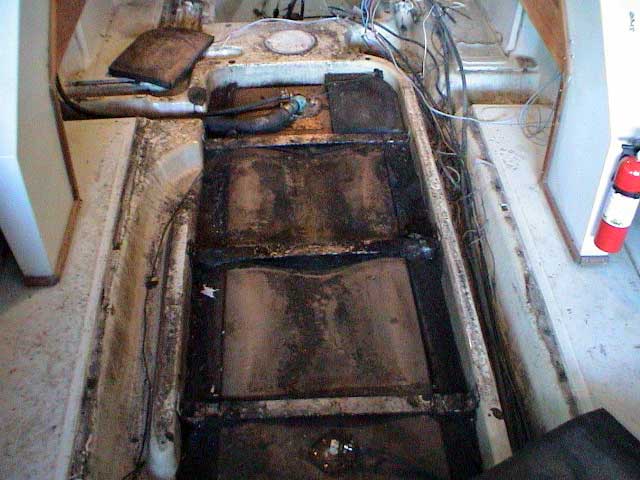
The fuel tank cavity should NOT have a path for water to drain into it from the center deck. The center deck section that covers the fuel tank should be sealed by caulk to the rest of the deck, and water on the deck should not be able to get into the fuel tank cavity. Water can come into the fuel tank cavity on the port side of the cockpit through channels molded into the hull liner. These channels are the pathways for the fuel filler hose and fuel tank vent hose to traverse across under the deck from the fuel tank cavity to the cockpit inwales and then up to the gunwales. If there was water flowing along that area it could drain into the fuel tank cavity.
You can get an idea of where these channels are located from the image below:
See more of the construction of the hull under the deck in the many images in these articles from REFERENCE:
http://continuouswave.com/whaler/reference/centerDeckRepair.html
http://continuouswave.com/whaler/reference/outrageRestore.html
Another path to get water into the center fuel tank cavity is via the holes in the starboard wall of the cavity that connect to the rigging tunnel. If the rigging tunnel water level rises high enough, water can flow from the rigging tunnel into the fuel tank cavity.
As to how water gets past the two cockpit covers and into these areas, that mystery cannot be solved without a close visual inspection.
Re: 1988 REVENGE 20 W-T: Water In Fuel Tank Cavity
Thanks for the pic. I had the same thoughts about the two tunnels on the port side. I was wondering if I could run a bead of removable caulking around the base of the kick panel that covers the fuel hoses? That is the only spot I can see for water getting into the fuel tank cavity.
-
Vance's Revenge
- Posts: 116
- Joined: Wed Nov 25, 2015 2:37 am
- Location: Northern California
Re: 1988 REVENGE 20 W-T: Water In Fuel Tank Cavity
I have been re-doing a Revenge 22 and decided to stop water from entering the fuel tank cavity. Three entry points have been mentioned above.
I don't think caulking would work on the kick panels but may slow some water down and reduce the amount that gets into the cavity.
Instead of long fuel and vent hoses traveling down the gunwale and under the floor to the tank, I made an aluminum manifold that seals to the floor for the fuel hose and vent hose. This stops the hoses and separates them at the floor deck. The hoses from the fuel fill on-deck on the gunwale and vent go from the gunwale and side of the boat down to the top of the manifold that is sealed to the floor.
Under the floor the hoses attach from the bottom of the manifold and go to the fuel tank. On the starboard side I'm going to seal the open section of the floor behind the kick panel with a plate made of fiberglass over 1/4-inch plywood; One 1/2-inch tube comes up through the plate 12-inches for the fuel tank sending wires. I will not seal that tube around the wires so the system will be vented. What this means is the boat would have to have 12-inch of water on the deck before any goes under the floor to the fuel tank cavity.
You have to remember that there is a drain hole that is supposed to allow water to run from the tank cavity into the starboard rigging tunnel. Water will also run backwards from the rigging tunnel into the tank cavity. Water not only enters the rigging tunnel from the drain sump at the stern on Revenge models; it will enter under the helm and starboard cabinet where the control cables go down into the rigging tunnel.
My boat is still in construction. I have filled and sealed the square entry hole in the floor under the helm cabinet, sealed the drain hole from the tank cavity to the rigging tunnel, and blocked the rigging tunnel under the floor just up from the drain sump at the stern. I will be running all of my control cables and necessary wiring down the starboard gunwale to the rear of the boat.
I also installed a drain tube from the tank cavity to the under floor fish box just to check periodically and see if any water got by my system. I'm not putting any foam in my tank cavity when I install my new fuel tank.
Hope these ideas help.
Re: 1988 REVENGE 20 W-T: Water In Fuel Tank Cavity
Vance's Revenge wrote:Three entry points have been mentioned above.
Please mention the three entry points you are referring to in your comment. Explicitly listing the three points will be useful for readers. Thanks.
-
Vance's Revenge
- Posts: 116
- Joined: Wed Nov 25, 2015 2:37 am
- Location: Northern California
Re: 1988 REVENGE 20 W-T: Water In Fuel Tank Cavity
There were actually [four (or perhaps six) points of water entry into the central fuel tank cavity] in my boat because it has an electronic fuel sending unit:
--(1)behind the port kick panel where the fuel and vent lines run under the floor. Water runs off the floor and down the fuel line rigging tunnel in to the tank cavity. This is supposed to run across the tank and out the exit hole into the starboard rigging tunnel.
--(2)behind the starboard kick panel there is a gap in the floor next to the side of the boat where water runs off the floor down into the startboard rigging tunnel.
--(3)a hole between the starboard rigging tunnel and the top right side of my fuel tank cavity where the fuel sending wires went through. This was not sealed.
--(4)water from the Starboard side rigging tunnel runs backwards through the drain hole for the fuel tank to the starboard side rigging tunnel.
Actually there was no sealer between the underside of the floor cover and the starboard side top of the tank cavity. So water could run between the top of the tank cavity and the starboard rigging tunnel into the tank cavity as well.
On Revenge models a section of the floor was cut out and the steering lines and wiring to the motor and stern light were ran down under the console into the starboard side rigging tunnel. Therefore any water that runs under the starboard console runs into the starboard rigging tunnel and then can run into the tank cavity. It would have been better and cleaner if Boston Whaler ran this rigging along the starboard gunwale similar to other windshield boats.
The system was designed this way with the idea that the closed cell foam in the tank cavity would not absorb water. We all know now that is false. My boat had sat for over five years in California heat and still had at least 5-inches of water and saturated foam at the bottom of the tank cavity. The fuel tank was encased in powdery white and green oxidation that ate completely through in many places. It is a terrible design thinking that saltwater should flow over an aluminium tank encased in foam.
As my boat is a Revenge there is no reason to use the right [Starboard] side rigging tunnel other than for the fuel line and this is routed behind the tank cavity. My plan is to completely seal up the Starboard side rigging tunnel so only the drain sump is being used.
My attempt to solve the problem:
--make the fuel line and vent hose manifold I described above. This seals at the floor so the fuel fill and vent hoses feed to it from the top and stop at the floor. Then under the floor the fuel fill and vent hoses feed from the manifold to the tank.
--make a another floor section to fill the hole on the starboard side behind the starboard kick panel. I also will have one 12-inch-long tube that is sealed in this section that my fuel tank sending wires will come up through. This will be sealed with sealant to prevent water from getting under the floor and the tube will not be sealed around the wiring so the system can vent through that tube. Water will have to be at least 12-inches deep on the floor before water can get down that vent tube.
--[water entering via the cable routing hole to the tank cavity] is taken care of when I prevent water from getting into the starboard rigging tunnel.
--fill and seal-off the drain hole from the tank cavity to the starboard side rigging tube.
--[sealant between the underside of the floor cover and the starboard side top of the tank cavity will] not [be] necessary if I'm successful at preventing water from getting under the floor and into the starboard rigging tunnel.
--fill and seal the cutout for the steering and wiring in the floor that is located in the starboard cabinet
--to prevent water from running up the starboard rigging tunnel from the drain sump. I made a wall in the starboard rigging tunnel up under the floor that will seal off the starboard rigging tunnel from the drain sump. The drain sump will function normally with water running off the floor. I also installed a drain plug in the wall I made in the starboard side rigging tunnel to check periodically to ensure it is dry.
--install a drain tube from my tank cavity to my under floor fish box. I have a plug there that I can pull to check and make certain the fuel tank cavity drains if water does get in there.
I will not be adding foam in my tank cavity when I install my new tank. I have strengthened the floor of my tank cavity with fiberglass and epoxy that conforms to the angle of the bottom of the fuel tank and carries the weight of the tank. I feel that without the support of the foam the tank cavity would receive tremendous stress it was not designed for from the weight of the fuel tank and pounding of the boat.
Re: 1988 REVENGE 20 W-T: Water In Fuel Tank Cavity
Thanks for the comprehensive expansion of your comments.
Regarding water being able to enter the rigging tunnel on the starboard side under the helm console, on my c.1990 REVENGE boat there is a flange fitting attached to that deck opening that creates a lip around it that is about 2-inches high. This tends to prevent water on the deck from running over the opening and flowing into the rigging tunnel, as long as the water on deck is not higher than 2-inches.
As for relocation of all rigging to be out of the rigging tunnel on a REVENGE model, I have done that in a partial manner. The only rigging lines left in the rigging tunnel on my REVENGE are the hydraulic steering lines and one SONAR transducer cable. To move the hydraulic steering lines out of the rigging tunnel would require replacing the existing lines with longer (and more flexible) lines, and that would be expensive and quite a project. I intentionally left the SONAR line in the rigging tunnel (as the only electrical cable) in order to keep it away from the other engine electrical cables that I moved to run under the gunwales. The physical separation of the SONAR cable from other electrical cables improves the isolation of the SONAR and reduces interference from electrical noise and other signals to the SONAR receiver.
-
Vance's Revenge
- Posts: 116
- Joined: Wed Nov 25, 2015 2:37 am
- Location: Northern California
Re: 1988 REVENGE 20 W-T: Water In Fuel Tank Cavity
Hi Jimh,
My Revenge is a 1980 22 footer. Between 1980 and 1990 Whaler must have realised the problem and adjusted that access with the 2" lip you describe. Water in the Starboard side rigging tunnel is not a problem if the tunnel is sealed from the Fuel Tank Cavity. The original design would have been fine if the closed cell foam actually didn't soak up water over time.
Running your transducer coax up your rigging tunnel to be separate from your Tachometer and other engine wiring is a great idea. Although I'm a long ways from wiring my Revenge in my other boats I run the transducer coax around my port gunwale and mount the head unit on the port/passenger side of the dash. I would rather have the unit head on the drivers side but I was afraid of the noise from the tach. Your way has the best of both.
If my boat was a center console boat. I would do the same manifold process with the fuel/vent lines to the tank, install the drain system for the fuel tank cavity to the fish box and seal the drain hole from the tank cavity to the starboard side rigging tunnel. Then apply sealant along the top starboard side of the Fuel Tank Cavity when I installed the floor. This should prevent water from entering the fuel tank cavity; but the starboard rigging tunnel would work as designed.
The frustrating part of this for me is by the 1980's Boston Whaler had been making boats for over 20 years. It is impossible to believe that Whaler didn't know by then that closed cell foam soaked up water and they didn't make simple changes to fix the problem.
One example. The starboard side rigging tunnel was designed to trough water that entered the boat. While sitting the tunnel is designed to actually fill and works terrific. But Boston Whaler included a rope in the tunnel to aid in rigging. Great idea--right? To install this rope they drilled a hole at the bow end of the tunnel, ran the rope through the hole and simply tied a knot to prevent the rope from pulling through. This hole they drilled was not sealed in any manner (at least on my boat it wasn't) and water travels around the rope and down into the internal part of the hull with no way to escape. I see this stuff and think, "What the heck were they thinking?'
Don't get me wrong--great boats--but I guess the thought process was different back then. That is another fix. I removed the rope because I will not be using the rigging tube and sealed the hole. If I were going to use the rigging tunnel I would seal the hole and install as stainless U-bracket to tie the rope to.
Re: 1988 REVENGE 20 W-T: Water In Fuel Tank Cavity
Fantastic info. Some pictures would be great when you get the manifolds in place. My Revenge has been covered with two tarps the past two months and I still have water getting into the fuel tank cavity. I, too, did not foam in-place my rebuilt tank; I just used foam mats to hold it in place. I will take up the floor again in the spring or summer to be sure the tank hasn't moved around. As to how the water gets in there with two covers on the boat, I still have no idea. I may just lay in there next rain storm and try to see where it's coming from.
Re: 1988 REVENGE 20 W-T: Water In Fuel Tank Cavity
Vance's Revenge wrote:...Boston Whaler included a rope in the tunnel to aid in rigging.
I am not certain your conclusion that the rope you found in the rigging tunnel which was installed in a sloppy manner that encourage water leakage was done by Boston Whaler. I do not recall any prior mention of a rope in the rigging tunnel in other REVENGE models. In the era c.1988 when your boat was built by Boston Whaler, the factory did not perform the rigging of the engine. The boats were sold without engines and a dealer would install the engine. Perhaps the rope in the rigging tunnel was put there by a dealer during installation of rigging or by a previous owner of the boat.
-
Vance's Revenge
- Posts: 116
- Joined: Wed Nov 25, 2015 2:37 am
- Location: Northern California
Re: 1988 REVENGE 20 W-T: Water In Fuel Tank Cavity
Hi jimh,
You may be correct. It never crossed my mind that a Dealer may have installed the rope in the rigging tunnel. Somebody has been in there before. I read somewhere there was a recall in my boats years converting from a plastic to aluminum tank so I assumed that is why they were in there. I could tell because I noticed a difference in the screws in several places while removing the consoles and floor cover. My boat had an aluminium tank.
My boat is a 1980 which had the single floor cover unlike the later models such as yours. So my consoles had to come out to get to the tank. Which is a big job! I have since cut the floor so there are two sections now similar to your boats design. I will be supporting the cut with aluminium angle at the seam of the cut which is at the top end of the tank cavity. If Whaler did install the rigging rope they may have stopped doing it when they converted to two piece floors. The only thing that still makes be believe Whaler installed the rope is there was a plastic cap on the opposite side of the channel where the knot was. I wouldn't think that a dealer would have gone through that trouble.
Either way, whomever installed that rope wasn't thinking about water getting into the hull through the hole they had drilled.
Floater, I would be happy to send you pictures but I don't know how to post pictures on forums. If you would like to message me your email address I will email you anything you would like to see. My boat is not a Walk Through model but most sub structure is the same.