The drawing above is adapted from a drawing provided by Evinrude. The wiring is as shown in the original, but I have changed the nomenclature and callouts to reflect what I believe is better clarity. Each engine has its own dedicated cranking battery and battery selector switch. Switch S1 is associated with the Port engine; switch S2 is associated with the Starboard engine.
In normal operation, S1 is set to 1, and battery #1 cranks the Port engine. S2 is set to 2, and battery #2 cranks the Starboard engine. If either S1 or S2 is set to BOTH, then battery #1 and #2 are in parallel, and both engines will be cranking from the parallel combination of #1 and #2 batteries. If either S1 or S2 is set to BOTH, then both S1 and S2 should be set to BOTH to get the best configuration for parallel operation of battery #1 and #2.
In routine and normal operation there would be NO reason to set either S1 or S2 to the BOTH position. Each engine, Port or Starboard, should be easily started by its associated cranking batter alone (#1 for Port, and #2 for Starboard). The ONLY time that S1 and S2 would be set to BOTH might occur if the state of charge in battery #1 and #2 was so low that neither of them alone could crank over one engine. This situation should seldom or never occur, as the only load on battery #1 and battery #2 should be their associated engine, and both batteries should be easily maintained at full-charge by the charging current from their respective engines.
The two HOUSE batteries, #3 and #4, and not used in engine cranking and are isolated from the engine loads, but they are re-charged by the engines by the auxiliary charging outputs. As shown above, the Port engine will be charging #3 and the Starboard engine will be charging #4. The provision of the E-TEC engines to have auxiliary charging outputs greatly simplifies the charging of the house batteries. Without those auxiliary outputs, providing charging to the house batteries will become extremely complicated.
In the diagram above there are no loads shown attached to the HOUSE batteries. The house loads should be connected to the #3 battery and #4 battery, as desired. A typical arrangement will also provide a third battery switch (or perhaps even a fourth battery switch), which will handle the distribution of power from the two house batteries. Again, this is not shown in the diagram above. The arrangement for the house loads would typically provide a master switch or circuit breaker, which when set to OFF would completely disconnect all loads from the house battery.
All the battery negative terminals are wired in common. This is a 12-Volt DC system. In no case should batteries #3 and #4 be wired in series to get 24-Volts.
Loads like bilge pumps should be wired directly to only one of the four batteries through a fuse and control switch, by-passing the battery switches. This will permit the boat to be left unattended with all battery switches set to OFF, but with the bilge pump still having power supplied by one battery. If the pump runs excessively, it will only be able to discharge one battery. For advice on how to wire a bilge or sump pump, see a separate article at:
Cockpit Sump Pump
http://continuouswave.com/whaler/reference/bilgePump.html
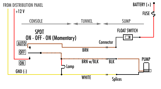
A typical wiring configuration is shown below:

Fig. 2: For automatic operation of a pump with the main power switch set to OFF, the pump is wired directly to a battery terminal through a fuse.
Typically the automatic bilge or sump pump would be wired to a house battery. This will prevent a cranking battery from being discharged. If one of the two house batteries becomes discharged, that battery will be re-charged as soon as the engine associated with it is running. If the primary power distribution wiring of the house batteries to their loads permits, all house loads can be moved to the other house battery while the dead house battery regains charge from the engine.