All boats 11 through 17 feet, capable of being equipped with a navigation light option, have wires installed at the factory. These wires are run behind the black insert of the heavy duty rub rail. If your boat is not equipped with navigational lights, a small plastic cap seals off where these wires enter the hull at the bow and rear interior top side. When navigational light kits are ordered, a wiring harness with in-line fuse and switch is provided along with a terminal block to connect the bow and stern light to the switch and battery.
All boats are equipped with either a circuit breaker or a fuse which protects the accessory wiring harness. On older boats, this is either an in-line fuse or circuit breaker located behind the switch panel inside the dash panels. Later boats (after 1986) have the circuit breaker located in the stern area of the boat close to the recommended battery location. On 13-foot models, a fuse is located behind the terminal block cover. The circuit breaker protects the wiring harness from electrical source (the battery) to the console or dash panel. Consoles and dash panels are equipped with a terminal block which carries current to individual accessory switches. There is room on the terminal block to add additional electrical accessory items.
Depth finders will work at high speeds, serving the function of continuously recording depths. They will assist in navigation and fish finding. To install a fathometer a transom mounted transducer must be installed. Do not consider a fathometer which requires through hull installation of the transducer. Because of the foam sandwich construction, through hull transducer installation is impossible, will create turbulence during high speed operation, and will interfere with trailer operation.
Mount the transducer on the PORT SIDE of the transom. The transducer in most cases will act as a mini-trim tab and can affect hull trim. When mounted on the port side, particularly on 17-foot models, the transducer will counteract port listing tendencies from propeller torque providing better hull trim.
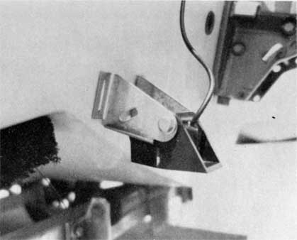
The transducer must be mounted flush and continuous with the boat's bottom and in an area where there is clear flow of water off the transom. Be sure the transducers is not in line with any spray strakes. A smooth flow of water must pass over the face of the transducer. If there is a space between the transducer and the boat it may be necessary to fill this area with compound or a facing piece. Some transducers are designed to hang just below the boat's bottom and pierce the flow of water.
Using a straight edge along the bottom of the boat, bring the transducer face down so that it just touches the straight edge. Fasten the transducer bracket to the transom. In most cases you will be outside the transom wood. However, the fiberglass is thick enough so stainless steel screws can be used. Bedding the transducer bracket and mounting screws with a marine compound is a good practice as it will also strengthen the installation. It may be necessary to depress the trailing edge of the transducer one or two degrees to ensure solid contact with the water. You will have to experiment. Consult the fathometer manufacturer's instructions as well.
Choose the location of the depth finder on the console carefully. Temporarily mount it on top of the console and turn it on to check its effect on the compass at various headings. If deviation occurs move the sounder as far away as practical. Record deviation at various headings for future reference. Remember, space on each model's console is limited and some of the larger fathometers may not fit.
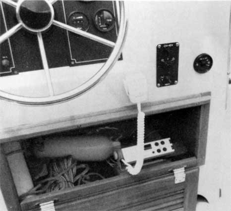
Marine VHF or CD radios, if mounted, should be in a protected location. On 11, 13, 15, and 17-foot models this will require special custom shelves or brackets to properly house the radio out of the weather and spray. On 17-foot Montauk models radios can be mounted on special brackets secured and hung from the console interior or a shelf built up from the console floor. On 17 Super Sport models and Newport models custom radio compartments will have to be fabricated.
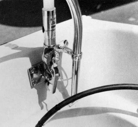
Antenna installation will depend on your model's configuration and your boat's canvas. If an antenna is mounted on the console, it will interfere with sun top and flying top set when these are in use. Generally, antennas on 17-foot models are best mounted in the rear either fastened to the hull or on rail mounted antenna bases. This keeps the antenna clear of canvas and the antenna coaxial cable can lead through the tunnel under the floor to the console. The antenna can also be stored along the side rail. Should you choose to mount the antenna on the console, it will not be possible to fly a sun top. However, if carefully positioned, the antenna can pass between the windshield zipper joint on the flying top set. The zipper will require minor modification. The use of a short barrel-type antenna mouned on the side of the console will eliminate this, but will reduce range. Check with your electronic dealer for further information. Antennas mounted to the console should be through bolted and a back up block provided behind the area. The bolts should be equipped with a lock washer and preferably aircraft lock nuts, as the antenna will be subject to constant whipping motion.
DISCLAIMER: This information is believed to be accurate but there is no guarantee. We do our best!
The page has been accessed times.
Portions Copyright © 2005 by James W. Hebert. Unauthorized reproduction prohibited!
This is a verified HTML 4.0 document served to you from continuousWave
URI: http://continuouswave.com
Author: Adapted to HTML by James W. Hebert
This article first appeared December 28, 2005.