In regard to a 2002 170 MONTAUK 17, Boston Whaler has provided a very detailed schematic diagram of all the wiring on the boat, including the wiring of the navigation lighting circuit.
I don't know if the detailed diagram is included in the owner's manual, but the diagram is available from Boston Whaler on their website. For help in locating the diagram (and other resources related to a particular year and model boat) see the advice given in the forum THE GAM at:
How to find Original Boston Whaler Diagrams and Drawingshttps://continuouswave.com/forum/viewtopic.php?f=4&t=9897In the case of the electrical schematic drawing for a 2002 170 MONTAUK, the beautifully detailed drawing can be found at this URL:
WIRING DIAGRAM 170MT-02
https://www.bostonwhaler.com/content/dam/boston-whaler/technical/resources/170-Montauk-Wiring-Diagram-Assembly-2002.pdfThe combined sidelights lamp is connected to wire number 203, a 14 AWG conductor with GRAY insulation for the positive or switched circuit. This is indicated on the drawing as "203-14 GRY".
The other conductor from the combined sidelights lamp is connected to a wire number 204, also a 14 AWG conductor with BLACK insulation for the unswitched or negative circuit. This is indicated on the drawing as "204-14 BLK".
The positive conductors are connected to the +12-Volt power distribution, typically with fuse protection for each circuit.
The black conductors are connected to the negative bus bar at the console, which in turn connects to the negative post of the battery.
The gray conductor is connected to switch contact "3". This circuit is also used to power the COMPASS light, which seems sensible, as if the boat is underway the compass should also be illuminated. That circuit is carried on wire 207-14 BLU.
The gray-white conductor is connected to switch contact "2". This circuit carries power to the WHITE ALL-ROUND lamp via wire 205-14 GRY/WHT.
The wiring at the switch is rather clever. If you study the action of the switch, you will see how the three lamps (COMPASS, SIDEIGHTS, WHITE ALL ROUND) are controlled.
SWITCH DETAILS
Multi-position electrical switches can be very complicated and have very specific switch actions, which is to say, not all switches are exactly the same. The switch used by Boston Whaler in the OEM build of the boat was a specific model with specific action at the contacts.
A good first step will be to carefully inspect the wiring at the switch. Verify that the six conductors that connect to the various contacts on the switch are all in the correct locations. Below is an excerpt from the drawing which is labeled DETAIL 1 and shows the connections to the switch that controls the three lamps involved.
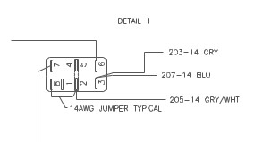
- Fig. 1. A portion of the schematic diagram that shows the details of the connections to the switch that controls the navigation lamps and the compass lamp. The GRAY conductor is for the sidelights lamp; the BLUE conductor is for the compass lamp; the GRAY-WHITE conductor is for the white all-round lamp.
- navLtsSwitchDetail.jpg (7.09 KiB) Viewed 1439 times