Overhaul Fuel Delivery on 1987 REVENGE 22

Repair or modification of Boston Whaler boats, their engines, trailers, and gear
rnln
Posts: 70
Joined: Mon Aug 23, 2021 6:15 pm

Overhaul Fuel Delivery on 1987 REVENGE 22

Postby rnln » Sat Jan 27, 2024 7:28 am

Give me advice for running fuel hoses from the fuel tank to the engine [on a 1987 REVEVGE 22].

IMG_2329.JPG
Fig. 1. Photo of rigging.
IMG_2329.JPG (221.55 KiB) Viewed 1177 times


As seen in Figure 1, at the moment the are two small-diameter copper flexible tubings along the starboard side of the aft below deck livewell running toward the engine from the fuel tank,

I remember I read somewhere "no copper pipe on boat.”

Q1: what should I do now?

Q2: should I keep the copper tubing?

Q3: should I use stainless steel tubing?

Q4: should I use brass pipe?

The present fuel line rigging is:
Tank -> 3/8-inch hoses -> copper pipes -> hoses again -> engine.

I would like to add a fuel-water separating filter on the gunwale [upstream] of the engines.

ASIDE: Hi everyone,
I was here more often several years ago after I bought a fixer-upper 1987 Revenge 22. After a year working on it almost every weekends and nights, I got busy with family things and slowed down a bit. I can be back to it now, finishing it up as soon as I can.

Jefecinco
Posts: 1601
Joined: Fri Oct 09, 2015 6:35 pm
Location: Gulf Shores, AL

Re: Overhaul Fuel Delivery on REVENGE 22

Postby Jefecinco » Sat Jan 27, 2024 10:37 am

Use rubber fuel line approved by the USCG.
Butch

jimh
Posts: 11725
Joined: Fri Oct 09, 2015 12:25 pm
Location: Michigan, Lower Peninsula
Contact:

Re: Overhaul Fuel Delivery on REVENGE 22

Postby jimh » Sat Jan 27, 2024 5:59 pm

rnln wrote:I remember I read somewhere "no copper pipe on boat.”

Q1: what should I do now?
You should give the URL to an authoritative source for that prohibition in federal regulations that you think you read once somewhere.

rnln wrote: Q2: should I keep the copper tubing?
If you are going to overhaul the whole fuel delivery system, discard the copper tubings and any rubber hoses. Run new USCG-approved rubber fuel hose from the fuel tank pick up fitting, stop first at the fuel-water separating filter.

DO NOT MOUNT THE FILTER ON THE GUNWALES. Mount the filter to the inboard wall of the transom or the hull sides.

After the filter, insert a very good OEM quality new primer bulb so the direction arrow on the primer bulb points upward and toward the engine. The bulb should be close to the engine and in a handy location that can be reached easily.

After the primer bulb run more hose to the engine and into the engine cowling to the appropriate point in the engine fuel system.

Read about USCG fuel hose requirements, but don’t get confused about rules for newly built boats compared to existing boats. And be prepared to be shocked at the price per foot.

rnln wrote: Q3: should I use stainless steel tubing?
No—I have never seen this used on any outboard engine because the engine has to pivot and tilt.

rnln wrote: Q4: should I use brass pipe?
No. Where would you get flexible brass tubing.

The fewer connections in the fuel hose runs, the better the system will be.

NOW FOR YOU TO ANSWER:

Q5: are you running dual engines?

Your answer will solicit more advice.

rnln
Posts: 70
Joined: Mon Aug 23, 2021 6:15 pm

Re: Overhaul Fuel Delivery on REVENGE 22

Postby rnln » Sun Jan 28, 2024 3:54 am

Thanks Jefecinco and Jim for responding,

jimh wrote:Q5: are you running dual engines?
I am rigging the fuel system for twin Yamaha 70-HP engines.

Q6: should I use rubber fuel hose rated A1?

The old hose on the boat is rated A1.

I have to overhaul the whole fuel delivery system from tank to fuel-water separator filters to primer bulbs and to engine. And the total price almost knocked me off my chair.

Since I planned on having the filters on the Starboard [unclear] facing inward, I don't expect the fuel line section between the tank and the filters (hose and pipes) to be flexing at all. They are all stationary. The portion between the filters to the primer bulbs and to the engine will be flexible.

If I can get rid of those little pipes, there will be less connection points.

Q7: can two 3/8-ID rubber A1 hoses be bent 90-degrees to go through the access hole [between the live well and the aft cockpit starboard sump area]?

A plastic cover or protection is now in place at the access hole, and that reduces the room available; the opening is narrow.

Also, I will have to drill an additional or second access hole; there is only one access hole now.

jimh
Posts: 11725
Joined: Fri Oct 09, 2015 12:25 pm
Location: Michigan, Lower Peninsula
Contact:

Re: Overhaul Fuel Delivery on REVENGE 22

Postby jimh » Sun Jan 28, 2024 9:36 am

Rigging fuel lines for twin engine will usually employ two independent feeds from the fuel tank.

Q8: on the present fuel tank are there two separate fuel outlet fittings?

jimh
Posts: 11725
Joined: Fri Oct 09, 2015 12:25 pm
Location: Michigan, Lower Peninsula
Contact:

Re: Overhaul Fuel Delivery on REVENGE 22

Postby jimh » Sun Jan 28, 2024 9:52 am

rnln wrote:Q6: should I use rubber fuel hose rated A1?
Yes. For 70-HP engines you can use 5/16-ID hose, which will be smaller.

ASIDE: when this 1987 REVENGE 22 W-T was delivered to the selling dealer from Boston Whaler, the installation of engines and the rigging of the fuel lines would be done by the dealer as the buyer desired. There MAY have been an accommodation offered by Boston Whaler to the dealer, if the dealer knew the boat would be rigged with twin engines, to install two fuel lines up to the point where the dealer could access them easily. That point would typically be beyond the point where the lines came out of the aft center live well and entered the aft cockpit starboard sump area. At that point a dealer could easily attach rubber hoses. In that rigging the factory may have used copper fuel hoses.

I own a 1990 REVENGE 22 W-T, and it was originally rigged with a single engine, so only one fuel output fitting was provided, and the fuel line was a single rubber hose.

jimh
Posts: 11725
Joined: Fri Oct 09, 2015 12:25 pm
Location: Michigan, Lower Peninsula
Contact:

Re: Overhaul Fuel Delivery on 1987 REVENGE 22

Postby jimh » Sun Jan 28, 2024 10:36 am

For securing a rubber fuel hose at a connection, a barb fitting is normally used. The hose is compressed onto the hose barb. The compression is often seen done by a circular stainless steel strap that is tightened by a worm screw, but this method is not particularly elegant or the best choice. The sharp edges of the steel band can cut into a rubber hose.

An alternative method is to use a steel ring clamp fitting that is closed or tighten with a special tool, such as an Oetiker clamp. More about them at

Oetiker Clamps
https://continuouswave.com/forum/viewto ... ?f=6&t=622

Another option that is often seen is use of nylon ratchet clamps. Read more at

https://continuouswave.com/forum/viewto ... 096#p41096

The nylon clamps are often used at the primer bulb.

Also, the 70-HP Yamaha engines probably have a quick-disconnect connector at the engine cowling for attachment of the fuel supply hose. You may want to get new OEM Yamaha mating connectors to replace the c.1987 37-year-old connectors in use now.

rnln
Posts: 70
Joined: Mon Aug 23, 2021 6:15 pm

Re: Overhaul Fuel Delivery on REVENGE 22

Postby rnln » Mon Jan 29, 2024 5:44 am

jimh wrote:Rigging fuel lines for twin engine will usually employ two independent feeds from the fuel tank.

Q8: on the present fuel tank are there two separate fuel outlet fittings?


Yes. This is original when I first lift up the floorboard.

IMG_2340.jpeg
Fig. 2. The original fuel line rigging.
IMG_2340.jpeg (51.46 KiB) Viewed 1056 times

rnln
Posts: 70
Joined: Mon Aug 23, 2021 6:15 pm

Re: Overhaul Fuel Delivery on REVENGE 22

Postby rnln » Mon Jan 29, 2024 6:04 am

My boat was rigged with copper fuel line mixed with rubber hoeses as jimh described above.

However, I see that the fuel lines can come out directly from the fuel rank outlet to the rigging tunnel then curve to the sump area, and in this way there will uninterrupted rubber fuel lines going from the tank all the way to the filters, without having a 90-degree bend,

Q9: Do you think [the route shown below in Figure 3 is a better approach?

I will have to seal the existing hole in the live bait well and drill two more holes on bulkhead between the tank cavity to the rigging tunnel

I plan to line the new holes with fiberglass tubes. I will epoxy the tubes and smooth them out.

I am afraid the hoses will rub on the tubes and will be damage soon or later.

Q10: will rubber hoses run through fiberglass tubes eventually fail due to abrasion?

IMG_2339.jpeg
Fig. 3. Proposed routing of rubber fuel hoses.
IMG_2339.jpeg (54.38 KiB) Viewed 1058 times

rnln
Posts: 70
Joined: Mon Aug 23, 2021 6:15 pm

Re: Overhaul Fuel Delivery on 1987 REVENGE 22

Postby rnln » Mon Jan 29, 2024 6:05 am

I think I have [the special ] pliers [needed to squeeze closed an Oetiker ring]. I just have to find them.

rnln
Posts: 70
Joined: Mon Aug 23, 2021 6:15 pm

Re: Overhaul Fuel Delivery on 1987 REVENGE 22

Postby rnln » Mon Jan 29, 2024 6:12 am

Figure 4 below show the original installation of the copper fuel lines.

IMG_2337.jpeg
Fig. 4. The original installation of copper tubing for intermediate segment of the fuel lines.
IMG_2337.jpeg (59.65 KiB) Viewed 1051 times

rnln
Posts: 70
Joined: Mon Aug 23, 2021 6:15 pm

Re: Overhaul Fuel Delivery on 1987 REVENGE 22

Postby rnln » Mon Jan 29, 2024 6:19 am

I plan on installing the filters on the gunwale (red circles) because I saw some pictures of people doing so. But if you think it's a no no, I can do the second choice (blue circles) on the inwale.

IMG_2342.jpeg
Fig. 5. Proposed locations for fuel filters.
IMG_2342.jpeg (52.5 KiB) Viewed 1048 times


Please let me know what you think.

Or as shown in Figure 6, I can mount a 2x6 wood piece on the stainless steel bar and install the fuel filters behind it (purple).

Thanks.
IMG_2343.jpeg
Fig. 6. Alternate location for fuel filters.
IMG_2343.jpeg (143.81 KiB) Viewed 1045 times

jimh
Posts: 11725
Joined: Fri Oct 09, 2015 12:25 pm
Location: Michigan, Lower Peninsula
Contact:

Re: Overhaul Fuel Delivery on 1987 REVENGE 22

Postby jimh » Mon Jan 29, 2024 11:38 am

My advice for the location of the fuel filters is on the hull inwales, as seen in Fig. 5 with blue circles, but slightly more forward than indicated. If the hull inwale is curving there, you could make a fairing block to present a flat surface to the filter mounts. When mounting a canister-type filter, be sure you leave enough room below the filter to allow the filter to be unthreaded and removed without spilling out a lot of fuel into the boat.

Also, you could use smaller canister filters because the flow rate of fuel for a 70-HP engine will not require the typical rather large canister filters often used.

Another option is to use one large canister filter with a filter manifold that allows two inlets and two outlets. But using one large filter for both the inlet hoses and the outlet hoses will eliminate the total redundancy of using separate filters. If you are boating in areas where the gasoline for sale is not the best quality, perhaps two filters will be better.

My own boating experience is to have never had any bad fuel, and I have never had to change a fuel filter.

In addition to poor gasoline, another source of contamination in the fuel can come from sediments in the tank bottom. Sediments can exist without causing problems for a long time, but the sediments can be stirred up by operating the boat in rough seas. This occurred to a friend of mine when be bought a used boat that had been sitting for a long while without use; the fuel tank had a lot of sediment in it, and after ten miles in rough seas, a fuel filter clogged with filtered sediment and one of his engines stalled. His boat was rigged with twin engines and two independent fuel lines with separate filters. That allowed the voyage to continue on one engine to the nearest port, where repairs could be made.

jimh
Posts: 11725
Joined: Fri Oct 09, 2015 12:25 pm
Location: Michigan, Lower Peninsula
Contact:

Re: Overhaul Fuel Delivery on 1987 REVENGE 22

Postby jimh » Mon Jan 29, 2024 11:43 am

As seen in Figure 2, that second fuel line connecting to the fuel tank looks oddly done. I would examine the tank fitting there very closely to see what was done.

jimh
Posts: 11725
Joined: Fri Oct 09, 2015 12:25 pm
Location: Michigan, Lower Peninsula
Contact:

Re: Overhaul Fuel Delivery on 1987 REVENGE 22

Postby jimh » Mon Jan 29, 2024 11:45 am

As seen in Figure 4, I suspect the connection between the rubber hoses from the fuel tank and the copper lines was made underneath that plastic cover on the left of the photo.

ALAN G
Posts: 25
Joined: Sat Oct 17, 2015 10:57 pm
Location: Livermore, CA

Re: Overhaul Fuel Delivery on 1987 REVENGE 22

Postby ALAN G » Tue Jan 30, 2024 6:20 pm

I used to own an 1990 Revenge 22 with twin Johnson 120 hp outboards on a conventional transom (no Whaler Drive). When I bought it in 2012, I decided to change the fuel hoses on principle since the former owner said he never did.

Tank & Hose R&R 3a.jpg
Fig. 7. Original fuel system.
Tank & Hose R&R 3a.jpg (198.48 KiB) Viewed 1021 times


The original configuration of my 1990 is shown in Figure 7 above, and the perspective is looking aft.

Out of two fuel tank barb fittings ran two hoses shown at the bottom of the image. They ran aft thru the bulkhead that separates the fuel tank cavity from the insulated fish box compartment. The bulkhead was lined with a straight, short piece of PVC pipe. The hoses were supported by hose clamps as they ran aft along the stbd side of the fish well.

The two hoses turned 90 degrees to starboard through the bulkhead between the live well and the sump well on the starboard side. That bulkhead was lined with a 90-degree PVC pipe fitting and came out in the bilge compartment as high as possible.

The hoses terminated in a brass assembly that I would describe as two 90-degree pipe elbows screwed into a connecting pipe nipple. Threaded into each elbow was a hose barb fitting. The brass assembly was mounted in a teak cover plate which covered the bilge compartment. The brass assembly was mounted in a hole drilled in this cover plate and nuts held the assembly secure to the cover plate. Thus, the fuel tank hoses were connected to the hose barb below the cover plate, while the hose that went to the fuel primer bulb, fuel filter, and outboard were connected to hose barb above the cover plate.

This is difficult to describe without a picture, and while I don't have one of the "as found condition", I do have one of my final assembly, shown in Figure 8 below.


Tank & Hose R&R 9a.jpg
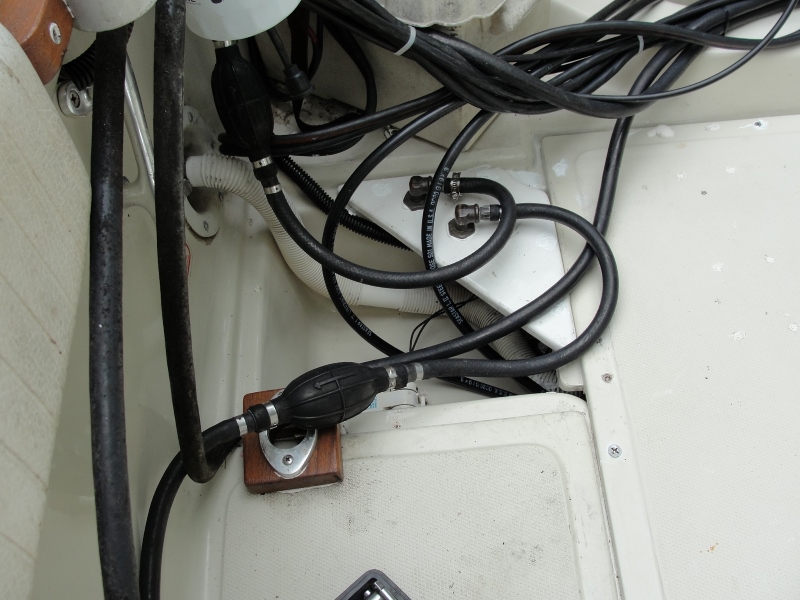
Fig. 8. Restored fuek system.
Tank & Hose R&R 9a.jpg (217.65 KiB) Viewed 1021 times


The original teak cover plywood had disintegrated and I replaced it with the white triangular piece you see with the two fuel fittings coming out of the top. You will have to imagine what it looks like underneath because I have no photo of that. But it is identical to what you see on top of the plywood. You can see the nuts that holds one side of each brass assembly to the plywood, the 90 degree elbows, and where the hoses are clamped to the fuel hose barb fittings.

Since my boat did not have any hard copper tubing, I cannot comment on the rnln configuration as to whether it is original Whaler installation or modified by a former owner. Mine was all rubber hose, save for the brass assemblies. I theorize that my boat came from the factory with fuel lines installed up to the bottom barbs of the brass assemblies, and the dealer would add the hose from the upper barb to the primer bulb, filter, and engine.

I hope this helps in your thinking about what to put back on your boat rnln. I would not be concerned about chafe where the fuel lines run thru the bulkheads, and you can line them with smooth PVC fittings like Whaler did mine. You can also caulk them in place inside the bulkheads which would further secure them against chafe.

If I can help further or answer questions, please reply.

Al

jimh
Posts: 11725
Joined: Fri Oct 09, 2015 12:25 pm
Location: Michigan, Lower Peninsula
Contact:

Re: Overhaul Fuel Delivery on 1987 REVENGE 22

Postby jimh » Tue Jan 30, 2024 10:38 pm

ASIDE: the difference in appearance of the aft starboard cockpit sump in Figure 7 and then later in Figure 8 is quite impressive, and it indicates a very significant restoration. Nice work.

The restored fuel system looks great, too.

rnln
Posts: 70
Joined: Mon Aug 23, 2021 6:15 pm

Re: Overhaul Fuel Delivery on 1987 REVENGE 22

Postby rnln » Thu Feb 01, 2024 1:46 pm

jimh wrote:As seen in Figure 2, that second fuel line connecting to the fuel tank looks oddly done. I would examine the tank fitting there very closely to see what was done.
Oh, sorry, I didn't explain. I took the photograph in Figure 2 right after I lifted up the center deck molded section that covers the fuel tank cavity. One of the hoses is not connected. The [second] fuel pick-up port was closed off.

Looks like the fuel supply from the fuel tank was using only one of the two fuel hoses to the engines.

The seller of this 1987 REVENGE 22 told me he emptied the fuel tank before he let the boat sit unused.
Last edited by rnln on Thu Feb 01, 2024 6:56 pm, edited 1 time in total.

rnln
Posts: 70
Joined: Mon Aug 23, 2021 6:15 pm

Re: Overhaul Fuel Delivery on 1987 REVENGE 22

Postby rnln » Thu Feb 01, 2024 2:05 pm

Thanks Jim and Alan very much for very detail info/explanation and pictures. I am confident to make my decision now.
Thank you.