Wiring Diagram for Older Boat
Wiring Diagram for Older Boat
[Seeks a wiring diagram for a 1984 Boston Whaler MONTAUK.] I need to re-do [the electrical power distribution] on my [Boston Whaler MONTAUK]. Thanks.
Re: Wiring Diagram for Older Boat
I don't know that there are wiring diagrams for specific model years and specific models of Boston Whaler boats from the 1980's, at least not for the smaller boats. Boston Whaler has published a very generic sketch of a typical small boat wiring in one of their older operator's manuals.
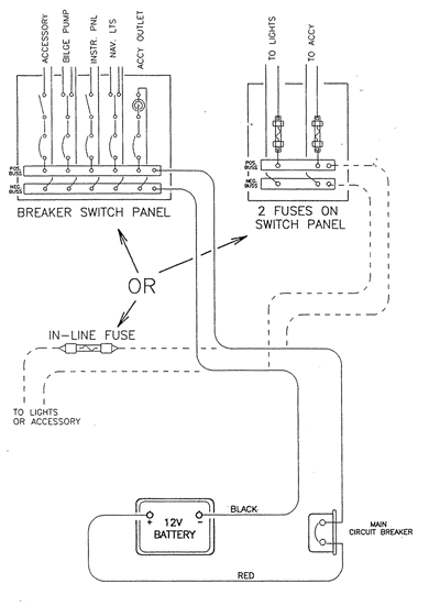
Generic pictorial diagram of Boston Whaler small boat electrical wiring
It is very unlikely that the electrical system on a 30-year-old boat has remained in the factory condition. It is also unlikely that you would want to restore the electrical system to its 30-year-old original configuration, unless you were attempting to build a museum exhibit of 30-year-old wiring practices in small boats. It is also unlikely that a comprehensive schematic or pictorial diagram of the wiring will be necessary to understand the arrangement, as all of the wiring and electrical components are generally in view, they can be easily observed, and the wiring was simple and straightforward.
Comprehensive Description of Typical Boston Whaler Small Boat Electrical System c. 1980
The 12-Volt DC electrical system of a older Boston Whaler boat was extremely simple. The electrical power wiring typically consists of a battery and a 30-Ampere (or higher) circuit breaker feeding a small power distribution bus panel at the helm area. Typically 8-AWG red and black conductors were used from the battery to the helm bus panel. The circuit breaker was located near the battery, often mounted to the cockpit bulwarks and enclosed in a light plastic shield housing to provide splash protection. The circuit breaker was similar to the Carling CLB series being made today.
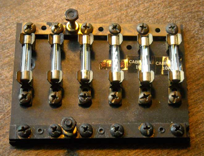
A typical 12-Volt DC Power Distribution Bus Panel used by Boston Whaler c.1980
See my article Secondary Power Distribution Refurbished on c.1990 Whaler for more details. I recommend some more modern components if you plan to refurbish the electrical system on your older boat.
On the dashboard there were typically three pull switches. One switch was a three-position three-circuit switch for controlling the navigation lamps. This wiring is described in detail in a REFERENCE article, Navigation Lamp Wiring, which also gives details about the Cole-Hersee switches that were used. They are still available. The other two switches were typically single circuit ON-OFF switches available to be used for various circuits. A typical clrcuit would be instrument illumination.
The wiring color codes used by Boston Whaler are also available in another REFERENCE article. See Marine Wiring Color Codes.
In some instances, a sub-feed from the secondary power distribution panel fed a group of three circuit breakers hidden inside the helm panel. The three branch circuits from the three circuit breakers fed the three instrument panel switches.
If your boat has an electric sump pump, you can find details of that wiring in another REFERENCE article. See Cockpit Sump Pump. The switch controlling a pump was usually a toggle switch with an ON-OFF-ON MOMENTARY action.
The wiring to the navigation lamps that is concealed inside the hull is described in an answer to a Frequently Asked Question.
Generic pictorial diagram of Boston Whaler small boat electrical wiring
It is very unlikely that the electrical system on a 30-year-old boat has remained in the factory condition. It is also unlikely that you would want to restore the electrical system to its 30-year-old original configuration, unless you were attempting to build a museum exhibit of 30-year-old wiring practices in small boats. It is also unlikely that a comprehensive schematic or pictorial diagram of the wiring will be necessary to understand the arrangement, as all of the wiring and electrical components are generally in view, they can be easily observed, and the wiring was simple and straightforward.
Comprehensive Description of Typical Boston Whaler Small Boat Electrical System c. 1980
The 12-Volt DC electrical system of a older Boston Whaler boat was extremely simple. The electrical power wiring typically consists of a battery and a 30-Ampere (or higher) circuit breaker feeding a small power distribution bus panel at the helm area. Typically 8-AWG red and black conductors were used from the battery to the helm bus panel. The circuit breaker was located near the battery, often mounted to the cockpit bulwarks and enclosed in a light plastic shield housing to provide splash protection. The circuit breaker was similar to the Carling CLB series being made today.
A typical 12-Volt DC Power Distribution Bus Panel used by Boston Whaler c.1980
See my article Secondary Power Distribution Refurbished on c.1990 Whaler for more details. I recommend some more modern components if you plan to refurbish the electrical system on your older boat.
On the dashboard there were typically three pull switches. One switch was a three-position three-circuit switch for controlling the navigation lamps. This wiring is described in detail in a REFERENCE article, Navigation Lamp Wiring, which also gives details about the Cole-Hersee switches that were used. They are still available. The other two switches were typically single circuit ON-OFF switches available to be used for various circuits. A typical clrcuit would be instrument illumination.
The wiring color codes used by Boston Whaler are also available in another REFERENCE article. See Marine Wiring Color Codes.
In some instances, a sub-feed from the secondary power distribution panel fed a group of three circuit breakers hidden inside the helm panel. The three branch circuits from the three circuit breakers fed the three instrument panel switches.
If your boat has an electric sump pump, you can find details of that wiring in another REFERENCE article. See Cockpit Sump Pump. The switch controlling a pump was usually a toggle switch with an ON-OFF-ON MOMENTARY action.
The wiring to the navigation lamps that is concealed inside the hull is described in an answer to a Frequently Asked Question.