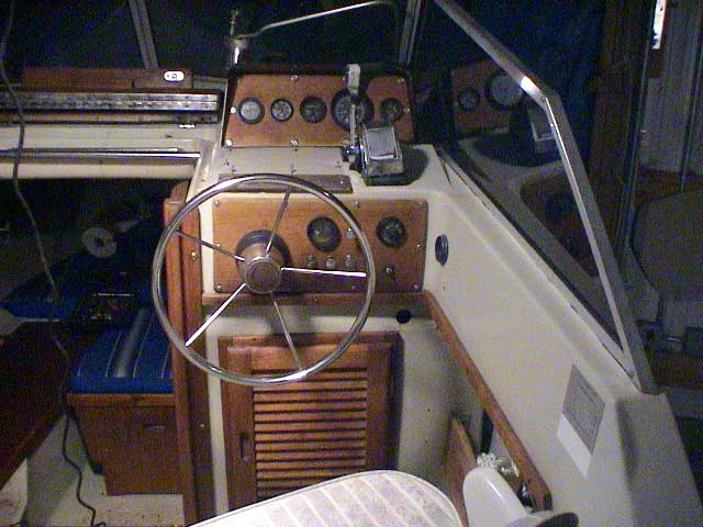
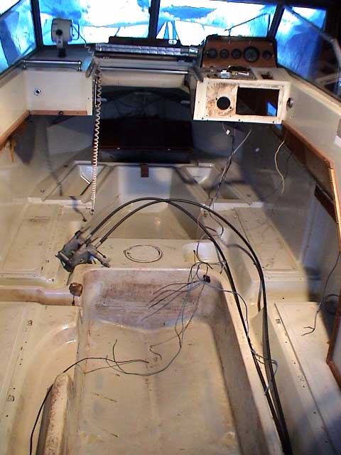
Here is an overall view of the starboard side of the cockpit as disassembly begins. Note all the teak components.
PhotoCredit: David Junker - Reference: 70-01
![[Logo: WHALER CETACEA]](graphics/cetaceaLogo230x60Trans.gif)
There have been many articles posted to our Whaler FORUM asking about the details of the Boston Whaler hull construction, particularly with interest in those unseen elements like the fuel tank system and under deck tunnels and troughs. Thanks to David Junker who sent these interesting photographs of the reconstruction of his 1980 Boston Whaler 22-Revenge, we get a chance to see what is under the cockpit floor.
Note on nomenclature: The actual Whaler OEM decal on the side of the hull refers to this model as a V-22 Revenge, but the 1980 catalog just refers to it as a 22-Revenge.
It is fortunate that David took this nice set of photographs. Often in the course of what can be some nasty work the camera is forgotten, and we can't benefit from seeing what was done and how it was accomplished. David says he took these shots to help him to remember how to put everything back together! That is a good idea, too.
If you tear up your Boston Whaler cockpit cover, you may not find exactly the same layout as seen here, but these photographs should give you a good idea of what lies beneath.
|
|
|
22-Revenge Console Here is an overall view of the starboard side of the cockpit as disassembly begins. Note all the teak components. PhotoCredit: David Junker - Reference: 70-01 |
 |
|
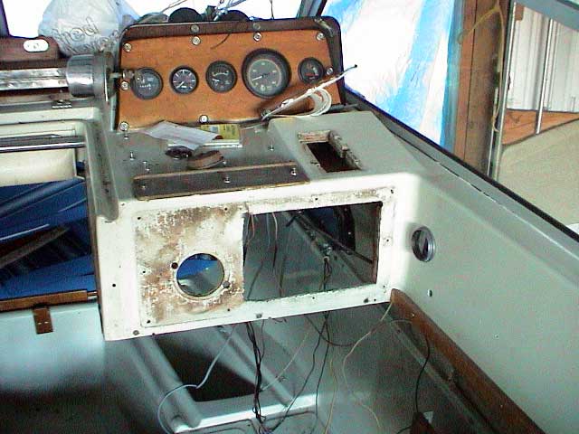
Early 22-Revenge Console The steering, the top mount engine controls, and the lower instrument panel have been removed. The bulkhead below the console has also been removed. In the cabin the wooden hatch cover for the starboard locker has been removed. PhotoCredit: David Junker - Reference: 70-02 |
 |
|
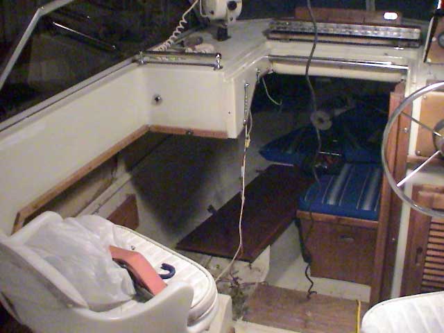
22-Revenge Deconstruction: Port Side On port the cabin bulkhead has been removed. The Vee-berth filler/Porta-Potti cover is still in place, as is the large hatch that forms the berth. PhotoCredit: David Junker - Reference: 70-03 |
 |
|
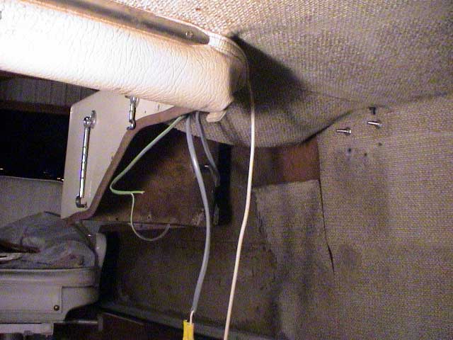
22-Revenge Cabin Headliner With the bulkhead out of the way, you can see the headliner. Note how a rolled vinyl pad protects you from bumps when entering the cabin. It also conceals wiring that runs across the cabin headliner. In a clever re-use of standard materials, the vinyl pad is held in place with stainless steel rub moldings normally seen on the gunwales. PhotoCredit: David Junker - Reference: 70-04 |
 |
|
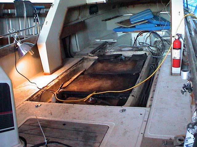
22-Revenge Cabin With the hatch covers removed, you can see the layout of the Revenge cabin. The central "deck" of the bow cabin is actually the deep in-deck storage locker from the Outrage that is normally covered with a large laminated hatch. Cables for the console come out of the deck at the end of the molded tunnel or trough to the stern. Next, David will remove that large molded cover that is screwed down in the central half of the cockpit, giving us a look at what is below. The dark rectangular piece in the center foreground is part of the companionway step. PhotoCredit: David Junker - Reference: 70-05 |
 |
|
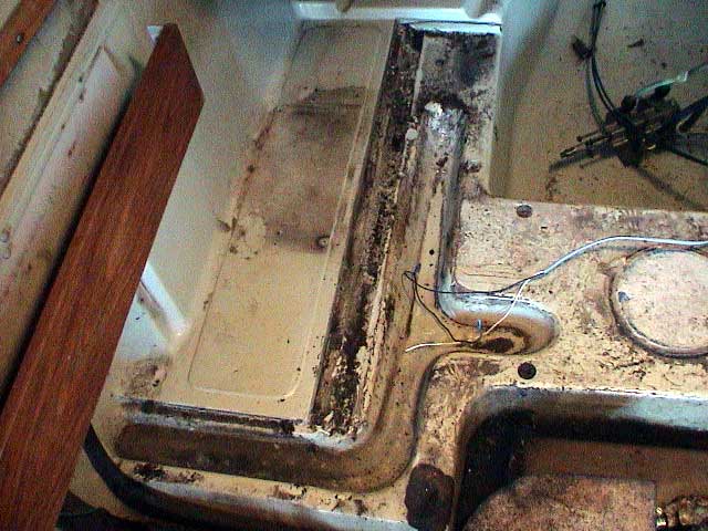
22-Revenge Cockpit Floor Details of the intricate molding of the liner half of the hull are seen here. This view is from mid cockpit looking forward on the port side. At the extreme left and bottom you can see the fuel lines coming down from the topside filler and vent. A trough molded into the floor appears to drain water from this area into the forward sump (cabin deck well) where a through-hull drain can remove it. The circular cap seen on the right is probably a sprue that was used to introduce and to vent the foam during manufacture. The fuel tank is foamed in-place in the cavity seen at the lower right. As you can see, in twenty years or more of use, a little mold and dirt can collect in these areas. Here it actually helps to make the contours more visible. PhotoCredit: David Junker - Reference: 70-06 |
 |
|
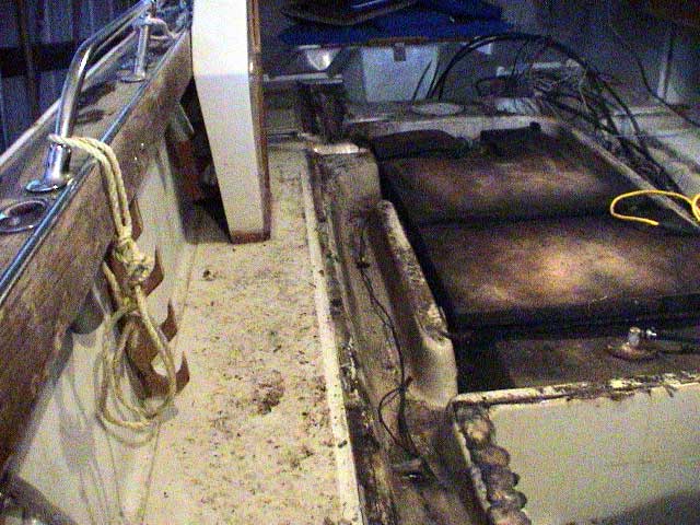
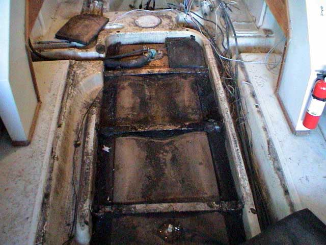
22-Revenge Cockpit Floor Details Looking forward from the port stern, the entire central cavity of the hull is seen with the foamed-in-place fuel tank occupying most of it. The wires in the trough are ground leads for the bonding system. PhotoCredit: David Junker - Reference: 70-07 |
 |
|
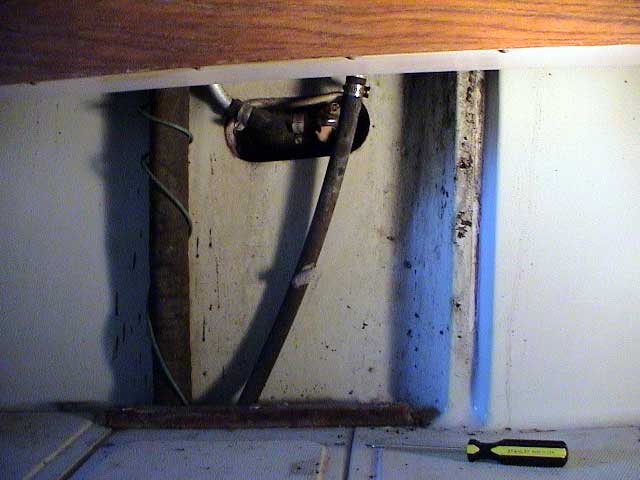
22-Revenge Fuel Fill and Vent On the port side the fuel filler tube (large diameter) and vent (small diameter) exit from under the cockpit floor and run up tp the fill fitting and vent on the hull topsides. Note how the green bonding wire is wrapped around the large fill hose. The vent also appears to loop above the outlet to discourage water coming in. These are normally protected by a thin laminated bulkhead cover. PhotoCredit: David Junker - Reference: 70-08 |
 |
|
Fuel Tank Fuel enters the tank via this fitting. An electrical fuel level gauge is used and a sender lead is attached. The dark foam appears to be in a thick sheet form that sits atop the 70-gallon tank. PhotoCredit: David Junker - Reference: 70-09 |
 |
|
Foam Fuel Tank Retainer The space between the tank top and the laminated cover is filled with this sheet foam. The cover for the in-deck live well is still in place, but it is about to be removed, too. PhotoCredit: David Junker - Reference: 70-10 |
 |
|
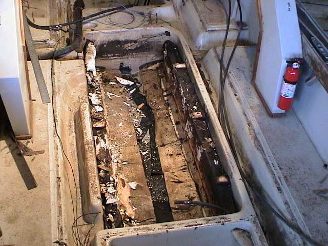
Fuel Tank Retainer With the top sheets of foam removed, the mechanical retaining trusses come into view. The retainers are aluminum, and they are fastened by screws into the hull cavity. The original tank was a polyethanlyne 70-gallon tank made by Tempo. There were 14-gallons of water surrounding the tank prior to its removal. The tank cavity does not drain until the water level rises to flow out the drain shown in another view. (See photo 70-11a.) PhotoCredit: David Junker - Reference: 70-11 |
 |
|
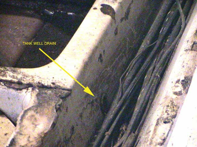
Fuel Tank Cavity Drain The fuel tank cavity has this drain to allow water trapped in it to drain to the rigging tunnel and thence to the stern sump. PhotoCredit: David Junker - Reference: 70-11a |
 |
|
Fuel Tank Cavity with Tank Removed The tank cavity without the tank in place. PhotoCredit: David Junker - Reference: 70-12 |
 |
|
Live Well with Fuel Line Shroud The fuel line runs into the rigging tunnel, crosses over to the live well, runs under a protective shroud through the live well, and finally into the tank cavity. PhotoCredit: David Junker - Reference: 70-12a |
 |
|
Cleaned Up Cavity I am sure that quite a bit of labor went into making the central fuel tank cavity look like this again. It is ready for fitting of a new tank. PhotoCredit: David Junker - Reference: 70-12b |
 |
|
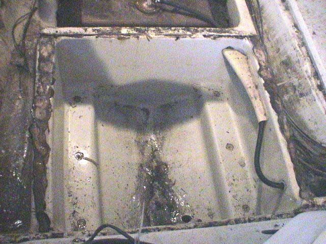
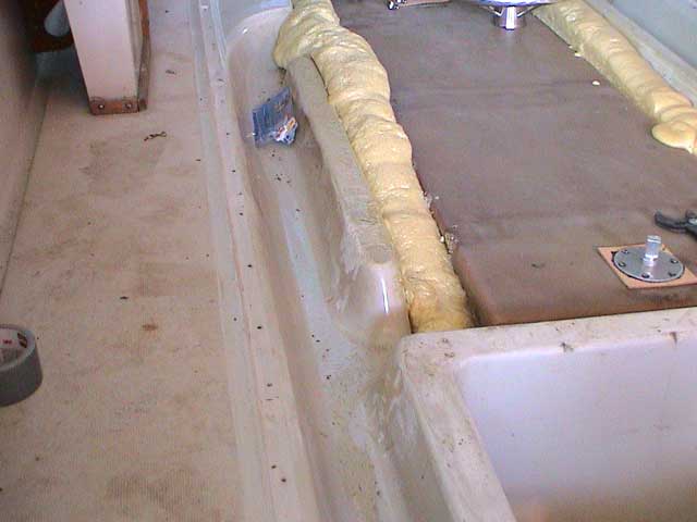
New Fuel Tank After clean up, the original tank was leak tested and found to be still in good shape . It was reinstalled and foamed in place. The foam has not been trimmed yet. The gelcoat on the cockpit liner has been nicely cleaned up. The purpose of this port trough is a bit of a mystery. It does NOT drain into a sump at the stern; it doesn't go anywhere. It would be interesting to hear from the original engineer or designer and to ask what his intention was for this part of the hull. PhotoCredit: David Junker - Reference: 70-13 |
 |
|
Gelcoat Blisters A closeup of the cockpit liner shows some blistering from water being allowed to sit in place for long periods. PhotoCredit: David Junker - Reference: 70-14 |
 |
|
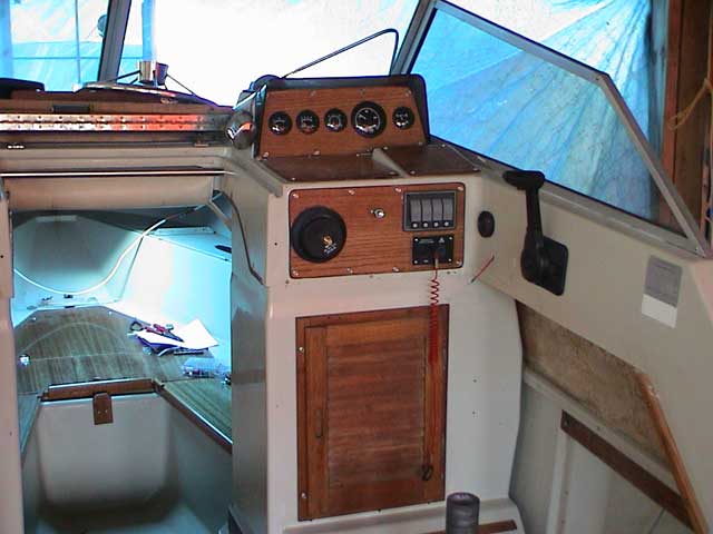
Finished Console The console is finished and most of the cabin is back together. David used a side-mounting engine control instead of the top-mount style normally seen on this console. PhotoCredit: David Junker - Reference: 70-15 |
 |
|
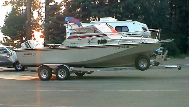
Reconstructed Boat After plenty of work, the boat is finally back together and ready for launching. It looks great! David also added a new Carnai "Concept" trailer. PhotoCredit: David Junker - Reference: 70-16 |
DISCLAIMER: This information is believed to be accurate but there is no guarantee. We do our best!
The page has been accessed 47310 times.
Copyright © 2003 by James W. Hebert. Unauthorized reproduction prohibited!
This is a verified HTML 4.0 document served to you from continuousWave
URI: http://continuouswave.com/whaler/cetacea/cetaceaPage70.html
This article first appeared January 5, 2003.
Last modified: Sunday, 01-Jun-2003 14:56:41 EDT
Author: James W. Hebert