Configuration for the em-trak R100 receiver USB interface to PolarView NS.
The specific port appears only when you have the R100 device connected.
A highly portable AIS receiver, chart plotter, and laptop combination for ship spotting from shore is described along with technical details of the interconnections.
Working just a few blocks from the Detroit River for the past 35 years has allowed me to see hundreds of vessels passing through Detroit during my frequent lunch time walks along the riverfront. Beginning in 2002 with the mandatory fitting of Automatic Identification System transponders on most commercial vessels, reception of AIS data has been a possibility and might add greatly to the fun of ship spotting. I have been monitoring the development and cost of small AIS receivers, and recently decided the cost–benefit ratio was about at a peak. I purchased a small AIS receiver that could be used with my laptop computer to receive and display ship data. I already had excellent chart plotter software which was capable of accepting input for AIS data. And I had a portable GPS receiver which would fix my position relative to the ships I was spotting. And, of course, I had a laptop computer to host the software and power all the devices. I will describe each element of my system in further detail.
For my portable AIS receiver I chose the em-trak R100 dual channel AIS receiver because of several factors. The most important is the dual-channel parallel receiver configuration. Ships use two frequencies to broadcast their AIS data. The best AIS devices employ two receivers that operate in parallel and independently receive data on either channel simultaneously. The em-trak R100 also employs a very modern VHF data receiver design; the actual receiver is implemented mainly in software using high-speed digital chips. (The em-trak receiver employs circuitry from SRT Marine Technology, which is the leader in AIS development and has designed and produced their own integrated circuit chips for this specialized application.) Power consumption in the R100 is so low that it can be powered by the 5-Volts available on a USB connector. The R100 only consumes 0.09-Ampere of current or 0.45-Watt of power when operating from the USB port. This is very important for a portable set-up, and it allows the receiver to be powered from the laptop computer, reducing the cord tangle and connections needed for portable use. However, in addition to the USB interface, the R100 also has a conventional 12-volt DC power input, and the R100 also has conventional NMEA-0183 serial data output. These arrangements permit the R100 to be run from boat power and integrated with a boat's dedicated chart plotter using the conventional interconnections of a fixed installation. Thus I can also use my R100 on my boat, when I am not on shore and ship spotting with it. (I will be testing it with boat systems next season.) The R100 also has a conventional SO-239 UHF series connector for the antenna. The antenna is the most important part of any receiving system, and being able to use a conventional external antenna with the R100 will give it maximum receiver range.
The em-trak R100 is a compact, low power consumption,
dual channel AIS receiver with both USB and conventional
NMEA serial data interfaces.
The R100 was just recently announced, and, with the manufacturer located in England, it was not immediately available in the United States of America. The primary distributor of the em-trak R100 in the USA appears to be WEST Marine. In November 2011 their on-line catalogue finally indicated the R100 was in-stock and ready for delivery at a price of $220. A pre-Christmas sale promotion offered a 15-percent discount and free shipping. Those two incentives removed any reluctance on my part to buy, and I ordered my R100.
For an antenna I am using a quarter-wave whip operated over the ground plane of the roof of my automobile. The antenna is mounted on a metal base with a strong magnet, and it attaches itself to the car roof magnetically. A full-size quarter-wave radiator over the large metal ground plane of the car roof makes for a very efficient and effective antenna. The coaxial feed line can be brought into the car interior by careful routing at a car door. Laying the feed line along a rubber gasket of the door edge will permit the feed line to come into the car interior without damage. A PL-259 connector on the feed line mates with the SO-239 on the R100.
It is not necessary to have a GPS receiver to plot the position of ships being received by the AIS receiver, but if you want to see the relative position of the targets to your location, you will need to provide information about your current position. A GlobalSAT BU-353 GPS receiver with USB interface is the perfect solution for a portable ship spotter. This $40 device is actually a very excellent GPS receiver, with near state-of-the-art sensitivity and position fixing accuracy. Again, the simplicity of the USB interface for power and data connection makes the BU-353 perfect for a portable ship spotting system. The BU-353 is also a low-power consumption device. It draws only 0.1-Ampere or 0.5-Watt of power from the laptop's USB port.

The GlobatSAT BU-353 is a proven performer as a USB powered GPS receiver.
To utilize the data received from the AIS transmissions and plot the position of vessels the excellent chart plotting software PolarView NS is my choice. I selected PolarView NS based on many factors. The software is being developed and deployed on three popular operating systems: Linux, MacOS, and Windows. The cross-platform development appealed to me as a MacOS user. Although there are software packages available specifically for the MacOS, I thought that PolarView NS would be likely to be in wider use due to the cross-platform capability, and this would tend to promote faster development and better support. Indeed, support from the developer, Polar Navy, for PolarView NS has been absolutely wonderful. Technical support inquiries are typically answered in a matter of minutes, and upgrades, enhancements, and bug-fixes are steadily released every few months. And, most important, PolarView NS is able to utilize the free digital charts for the USA published by NOAA, both the S57 vector format charts and the BSB raster charts. Finally, PolarView NS is modestly priced at only $40, making it a great bargain among computer-hosted chart and navigation programs. (For more on my use of PolarView, see another thread in our forum.)
For my system, the host computer and power source is my MacBook Pro. However, there is nothing MacOS-specific about my system, and it could be used in exactly the same manner with a host laptop running Windows or Linux. The laptop must have two USB ports for connecting the two external devices, the R100 AIS receiver and the BU-353 GPS receiver. Because the laptop is powering the two external devices, it may be prudent to have a 12-Volt power source for the laptop, such as the car's battery, to permit longer operating times.
Turning these separate components into a ship spotting system requires a bit of interconnection and configuration. The physical interconnection is very simple. The GPS receiver has an integral cable with USB connector, and it simply plugs into a USB port on the laptop. The AIS receiver has a mini-USB connector. A supplied 1-meter-long cable connects the receiver to the standard USB port on a laptop. The mag-mount antenna connects to the AIS receiver using mating UHF-series standard connectors. The physical interconnections are just "plug" but not quite also "and play." A bit of software interconnection of sources and destinations must be done manually.
The GlobatSAT BU-353 is provided with USB drivers for a variety of operating systems. To be honest, I have had the BU-353 receiver for several years, and I don't recall the precise details of the driver installation, but I can say it has been working flawlessly since day-one. It's a great GPS receiver for this application. It should be no problem to find drivers for any operating system and version.
The em-trak R100 comes with drivers for Windows and Mac. The drivers for the MacOS are identified only by the MacOS system name instead of the version number. This is a bit confusing, and I will clarify. From em-trak there are three driver versions provided: Panther (or MacOS 10.3); Tiger (or MacOS 10.4); and Snow Leopard (or MacOS 10.6). With my laptop running MacOS 10.6.8, I installed the driver designated as "Snow Leopard."
The GPS and the AIS receiver will both be sending data to the laptop via their USB connections. To route this data to the PolarView NS chart plotter application some type of process or daemon is needed. For PolarView NS, there is a companion application, PolarCOM, which performs the software data connection between hardware devices and the navigation application. It is in PolarCOM that we must make some configurations to get our ship spotting system working. PolarCOM has a rather sparse user interface, and some important features are hidden from the standard view. Let me help with some details.
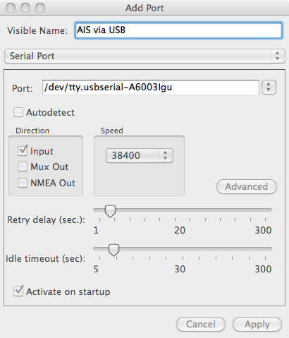
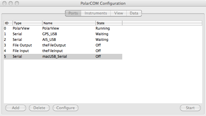
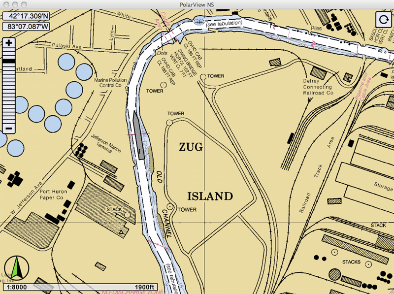
As set-up out-of-the-box, PolarCOM is configured with an auto-detect function that will locate most any source of data connected to the host computer and automatically configure it. However, only one auto-configure interface is recommended. To avoid any conflicts, it seems prudent to set-up two dedicated interfaces, one for the BU-353 and one for the R100. As I mentioned, Polar Navy provides excellent support. They have published an excellent Knowledge Base article giving the details of how to configure data connections using PolarCOM: Configuring serial port NMEA input in PolarCOM. Please refer to it to learn the steps necessary to reach the configuration screen. Once at the configuration screen, the settings I am using are show below in two screen captures. Note that Auto-detect has been turned off.
Configuration for the em-trak R100 receiver USB interface to PolarView NS.
The specific port appears only when you have the R100 device connected.
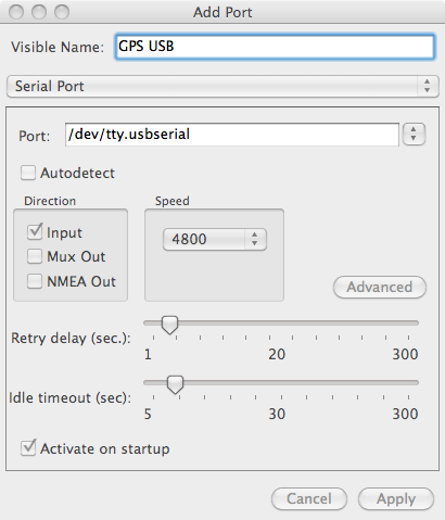
Configuration for the GlobalSAT BU-353 receiver USB interface to PolarView NS.
The information above will save you a lot of fuss in configuration and set-up if you are using these devices with PolarCOM. However, two final steps are necessary in the PolarView NS application. From the Ship menu, toggle ON the option Connect PolarCOM as well as the option Show AIS Ships. Now, let's go ship spotting!
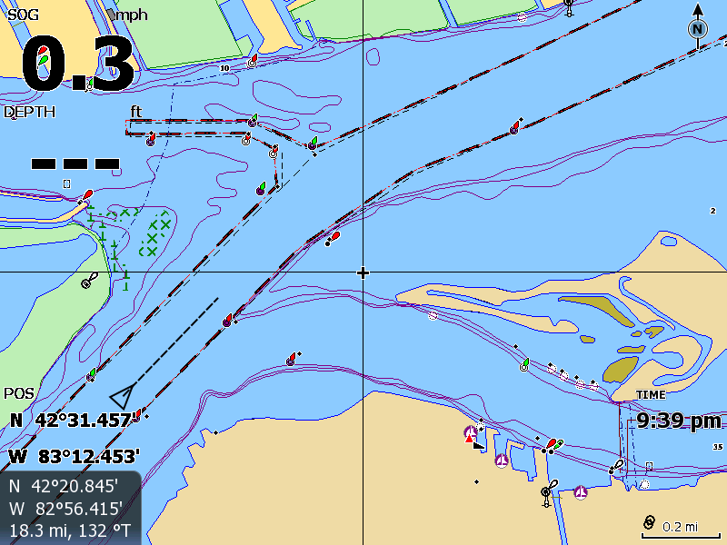
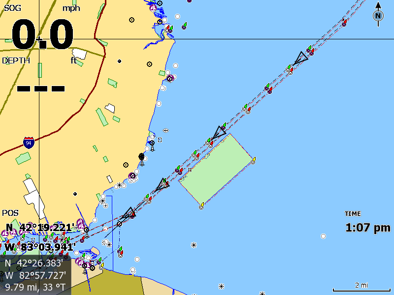
My initial foray with my new portable AIS ship spotting system was a noon visit to the Detroit River. I parked my car at the foot of 12th Street, on the north bank of the Detroit River. My laptop screen soon showed four ships nearby, two underway and two moored to the shore.
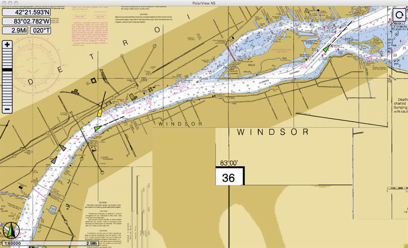
PolarView NS showing four vessels from AIS receiver data. My car is the yellow target. Vessels underway are shown in green and moored vessels in gray. The chart is a stitched composite of raster charts for this area. The large-scale river charts provide much more detail than the small-scale overall chart used for areas away from the shoreline, resulting in the tiled appearance.
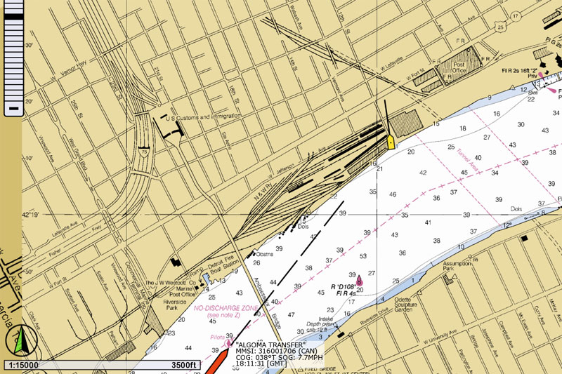
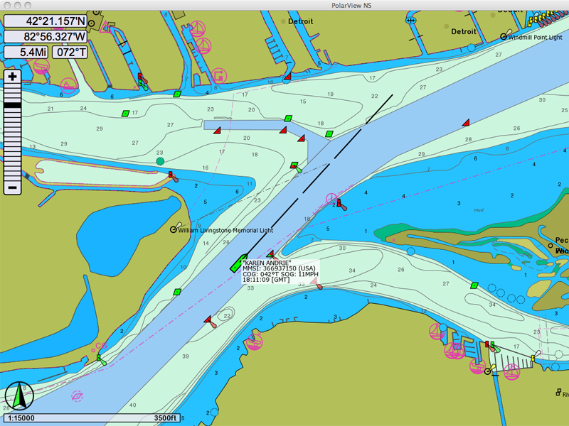
By zooming in on the chart plotter we can see more details of the AIS information. PolarView NS has calculated the closest point of approach (CPA) between my "ship" and the approaching vessel, and it concludes we are on a collision course. As a result, it marks the approaching ship in red.
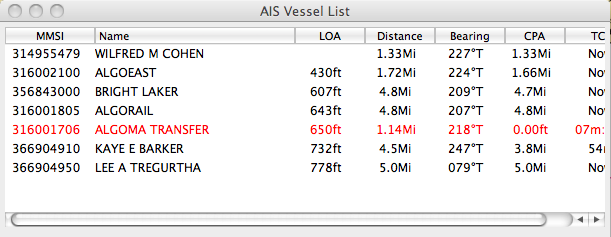
PolarView NS can also provide this tabular listing of AIS vessels in the vicinity. The right hand column (which unfortunately in this view is cropped) shows time to closest point of approach. Again, a red listing indicates a projection of a very close approach between vessels.
After sitting at the foot of 12th Street and marveling at this wonderful new AIS system, I noticed that a few miles away there was a vessel coming down the Rouge River. This meant several bridges had to open, affording a chance to do some ship spotting at close range. Without the AIS receiver data, I would not have known of this opportunity. I quickly drove my car over to the West Jefferson Bridge across the Rouge River, and parked close-by to wait. A few hundred yards away the vessel KAYE E. BARKER was slowly making way outbound toward the Detroit River. Here is a screen capture of the situation:
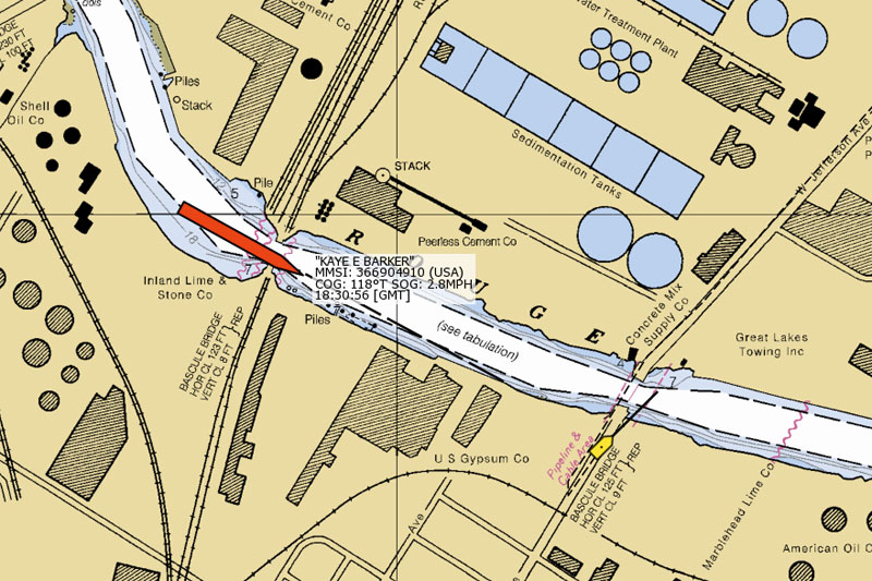
The KAYE E. BARKER is slowly approaching the West Jefferson Avenue Bridge. PolarView NS has used the dimensional data about the ship that it obtained from its AIS transmission to accurately draw the ship's icon to proper scale for length and width. The software also projects the ship's current heading to see the relationship with my "ship," which in this case is my parked car.
Of course, as the ship approached, I had to get out of the car and grab this picture, unfortunately with my cell-phone camera, and a bit over-exposed:

Going from the computer representation to the real thing, here is the KAYE E. BARKER as seen from the bascule bridge at West Jefferson Avenue and the Rouge River--and this is not a telephoto lens. She is so close you could easily toss something over to a crewman. The horizontal clearance at the bridge is 125-feet, and the ship's beam is 70-feet. There is little room for error in the transiting of this passage.
Here is my compact Ship Spotting rig ready for mobile deployment:
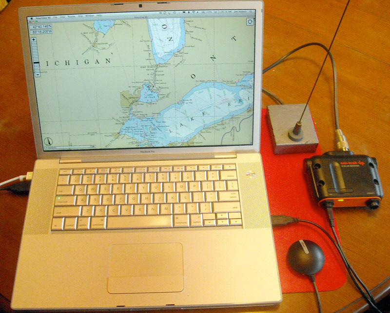
My road-warrior AIS receiver system: a MacBook Pro laptop running PolarView NS, a BU-353 GPS receiver puck, an R100 AIS receiver, and an old mag-mount quarter-wave antenna.
The em-trak R100 AIS receiver seems to be working very nicely. On my initial test the greatest distance to a vessel received was about 14-miles. That occurred when my car was parked in a parking garage on the fourth floor, so I had the benefit of some extra height in my receiver location. Two days later I drove up to Port Huron, and I used a new antenna, a 5/8th-wavelength vertical which should have some gain compared to the quarter-wave antenna. Sitting on a slight rise about twenty feet above the water, I was able to receive a ship signal from 19.8-miles out. Later I moved to what I thought might be a better location, a slightly lower spot right on the shore about a mile closer, but I lost the signal. It came back when the ship was about 14-miles away. As with any radio system, location, particularly antenna height, is very important in determining range of the system.

A Larsen mag-mount and 5/8th-wavelength 2-meter antenna worked well for the AIS receiver on 162-MHz. Best distance so far is 19.8-miles. This location is just north of Port Huron on the shore of Lake Huron.
PolarCOM is the application that actually provides the link between the GPS receiver and AIS receiver hardware and the chart plotter application, PolarView NS. PolarCOM provides a monitoring NMEA terminal which makes a great diagnostic feature. You can use the NMEA terminal to see the data coming from the AIS receiver. The data is not in a very human-readable form, but at least you can see that the receiver is putting out data on its NMEA interface. The terminal has a built-in pop-up selection for which interface you want to monitor, or you can monitor all of them at once.
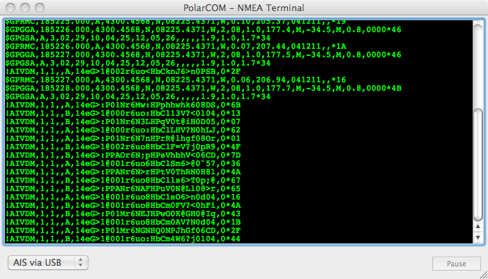
This NMEA terminal window shows the data being passed to PolarView NS by PolarCOM. The selector on the lower left allows you to pick which interface to monitor. The upper part of the terminal contain data from the GPS. The interface was then switched to the AIS interface, and the newer data (lower portion of listing) shows the AIS receiver output. The fifth position in the !AIVDM message is either "A" or "B", indicating the receiver channel. The mix of A and B data shows the receiver is reading both channels.
When presenting a vessel as an icon on a chart display, PolarView NS can show the vessel as a properly scaled outline of the hull rather than just a single point with a generic icon. The process that allows this is quite complicated. Automatic Identification System transmitters send a lot of data about the vessel, including the vessel length and beam, but the protocol is even more sophisticated than just that. Every six minutes the AIS transmitter also sends the location of the GPS sensor aboard the vessel by its offset from the bow and the Starboard gunwale. Until the additional information is acquired, PolarView NS draws the vessel with a generic icon at the broadcast position. Once the complete hull dimension and sensor position data are acquired, PolarView NS is able to render the vessel as a outline. The GPS sensor location is marked with a dot, and the hull outline is drawn around the dot with the appropriate offsets and heading. The two screen captures below demonstrate this process.
PolarView NS plots a ship position and heading with a generic icon if it has not received additional data about the vessel from the AIS receiver.

A few minutes later the same vessel as shown above is now rendered as a scaled hull outline. The black dot represents the actual position of the sensor on the vessel. The hull outline is drawn around the dot with the proper offset and scale. Note that not all GPS sensors are located on vessel centerline or at the bow. This view also shows a vector chart presentation in PolarView NS.

Here we see a vessel where the GPS sensor is not at the bow: the SAM LAUD in Lake St. Clair. Note the 18-mile range. The em-trak R100 AIS receiver seems to be able consistently to pull in ships in the 14 to 18 mile range with the receiver antenna just a few feet above water level.
Using some advanced features of the PolarCOM software, I was able to capture the AIS data output from the em-trak R100 receiver and play back the file to a serial port. (I describe the method in more detail below.) This allowed me to see a side-by-side comparison of the rendering of the AIS data on the HDS-8 and my laptop running PolarView NS. Other than setting up the HDS-8 serial port to interconnect with my virtual AIS receiver, there was no configuration necessary on the HDS-8. As soon as the HDS received AIS data, it began to overlay it onto the navigation charts and make it available in its vessel information tables.
The HDS-8 draws the vessel KAREN ANDRIE with a generic target icon.
PolarView NS draws the vessel KAREN ANDRIE with a scaled icon of the hull dimensions. The tabular data beside the icon can be toggled on and off with a mouse click. The size of the screen capture has been cropped to match the HDS screen size for comparison
I was probably going to be very happy with the display of AIS vessel targets on my Lowrance HDS chart plotter, until I saw what PolarView NS can do. However, the HDS does a nice job of providing AIS information in tabular form. Below is data from the vessel FEDERAL KASURA.
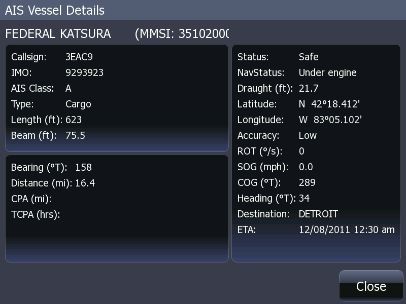
In AIS transmissions a great deal of static information about a vessel is also transmitted. The HDS-8 does a nice job of presenting the data in tabular form. Information like destination and ETA is manually entered by the crew into the AIS transmitter, and it may not be precisely accurate or up to date at all times.
PolarCOM is a very versatile component of the AIS system. For real-time operation, PolarCOM can be configured to receive data from various sources. I show above how PolarCOM has been configured to receive GPS data from an attached USB GPS receiver and AIS data from an attached USB AIS receiver. However, PolarCOM can also manipulate data to and from a file. In this way, PolarCOM can be used to capture real-time data from an AIS receiver and store it to a file. The data in the file can then be used as an input to PolarCOM, which will read the file data line by line at a rate which can be set in the interface. The result is the ability to record and playback AIS data.
To write data to a file, PolarCOM is configured with a file output port. The screen capture below shows typical settings.
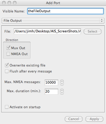
PolarCOM is configured to multiplex the data it is receiving and write it to an output file.
Once a data file is created that contains the captured AIS and GPS information, you can use that file as the input to PolarCOM, essentially playing back the recorded data from the file. The rate of playback can be selected, and in this way time compression can be applied. Here the rate is set to 20 lines per second, which telescopes the time interval rather nicely.
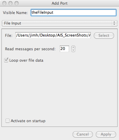
PolarCOM is configured to read data from a file at a particular speed.
After capturing about ten minutes of AIS and GPS information to a file, I verified that I could use the file as a source by replaying it with PolarView NS. The next step in the fun was to create a serial data output port on my laptop, and send the recorded data to it.
My MacBook Pro, like many modern laptop computers, does not have a native hardware RS-232 serial port. It is quite typical to use a USB to RS-232 adaptor to provide this sort of connection. Using a Keyspan HS-19 USB to RS-232 device, I was able to configure PolarCOM to sent the NMEA data it was handling to the Keyspan hardware RS-232 port. The configuration screen is shown below.

The Keyspan HS-19 USB to RS-232 serial device is configured to be a NMEA output.
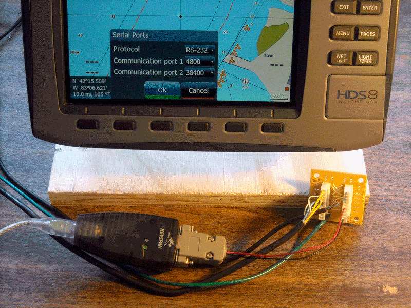
The final segment of the link between PolarCOM and the HDS was the wiring of the serial data interface. On the HDS-8 I set the serial ports for RS-232 and set the second port for 38,400-bps data.
The Keyspan HS-19 RS-232 serial output connects to the HDS-8 NMEA-0183 input via an adaptor I fabricated. (Earlier version shown here.) The small backplane with five-pin headers is my "universal" house standard interface wiring component.
An adapter cable for RS-232 on DB9 to my Universal NMEA-0183 interface was fabricated.
I made a DB9 to Universal NMEA-0183 five-pin header--my own house standard for NMEA-0183 interface. This transports the data from a file to the HDS-8. The wiring details of the RS-232 DB9 to Universal NMEA-0183 five-pin connector are as follows:
DB9F                       Universal NMEA-0183
TxData--< 3 <---(black---< A TX+
GND-----< 5 <---(white)--< B TX-
GND-----< 5 <---(white)--< C GND
        (No connection)--< D RX-
RxData--< 2 <---(red)----< E RX+
With all the ports configured, the operation of PolarCOM is controlled by starting or stopping the appropriate interfaces. This is accomplished on the PolarCOM configuration window.
There are five ports configured in PolarCOM. To play the file input to the RS-232 output, ports 4 and 5 are started manually.
I am very impressed with the flexibility of PolarCOM. It was able to interface to USB data sources, capture their data to a file, use the file as an input source, interface to a USB output device, and send the file data to a typical marine chart plotter over that hardware connection. That is a lot of capability for software to have!
Recently I was able to test the em-trak R100 NMEA-0183 serial data output via its power and data cable by connecting it to my Lowrance HDS-8 multi-function device. Since the test set up was going to be in my car rather than in the boat--the boat is laid up for the winter--I constructed a few cable assemblies to make the wiring somewhat modular and portable. I give some details below.
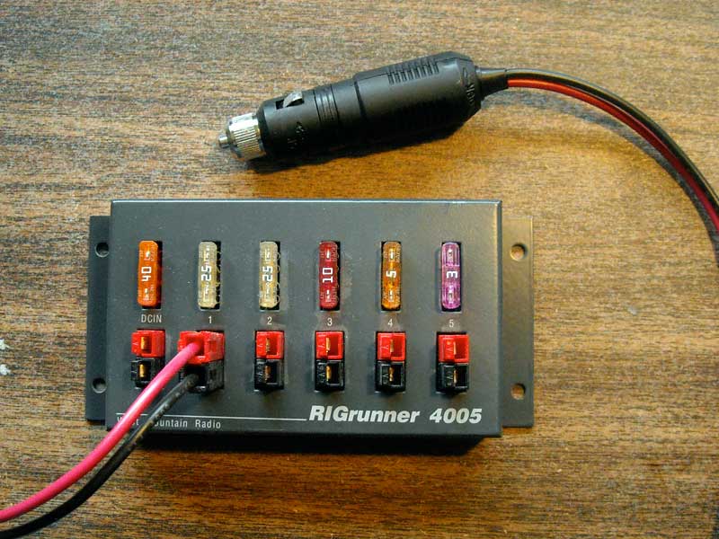
For temporary power in the vehicle, I connected my RIG RUNNER power distribution panel to the cigar lighter plug with this cable. The cable terminates with Anderson Power Pole connectors which mate with the RIG RUNNER. The HDS-8 and R100 were powered from the RIG RUNNER.

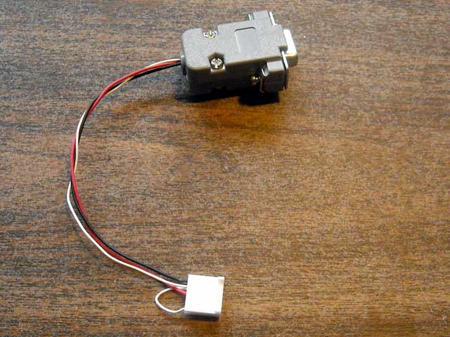
The 2-meter em-trak R100 power and data cable was mated to a 5-pin header connector for the serial data interface. The power leads were extended another meter and terminated with Anderson Power Pole connectors. I fabricated another Universal NMEA-0183 Interface backplane to handle the interconnection of the em-trak and Lowrance devices.
The em-trak R100 provides differential NMEA-0183 input and output. The wiring details of the connector for my Universal NMEA-0183 Interface are given below.
 em-trak R100 cable              Universal NMEA-0183
Transmit + -----(brown)---------< A TX +
Transmit - -----(blue)----------< B TX -
Power in -  ----(black)---------< C GND
Receive - ------(green)---------< D RX -
Receive + ------(white)---------< E RX +
The interconnection of the em-trak R100 and Lowrance HDS-8 worked perfectly. The serial data speed of the em-trak R100 is fixed at 38,400-BPS, so the Lowrance HDS-8 port must be set to match. The Universal NMEA-0183 Interface backplane handled the details of interconnecting the differential input and output of the em-trak with the single-ended input and output of the Lowrance. Targets immediately appeared on the HDS-8 display.
With the AIS receiver connected directly to the chart plotter for the first time, I saw four AIS targets heading across Lake St. Clair at a range of about ten miles from my location.
I have now verified the connection of the em-trak R100 to the Lowrance HDS-8 as it will be used on the boat next season. Of course, you could use it this way on land, too, but the USB interface is much simpler and requires much less cabling.
There remains at least one more test configuration to be configured and evaluated. I want to locate the em-trak R100 at a remote site and send its serial data via the public internet to PolarView via PolarCOM. To provide this function it will be necessary to employ some additional hardware. I anticipate using a MOXA Nport 5110 RS-232 to Ethernet serial data servier device to convert the AIS receiver's serial data to packets on the internet. When I complete this testing I will report results and details here.
Just for fun, I thought I would see how well the em-trak R100 AIS receiver might work when operating from my home, which is about 15-miles away from the nearest vessel that might be transmitting an AIS signal. For an antenna I used my television antenna. It's not your standard television antenna, but rather a VHF-Hi-band television ten-element yagi on a eight foot boom. I use it to pull in CBET-HD, a Canadian station that is 29-miles away and across the border, and it is aimed right at the Detroit River. (Why so much effort to get CBC? To watch Hockey Night In Canada in high-definition, of course!)
The TV antenna is really tuned for the 175-MHz to 216-MHz (Channel 7 to 13) and works great on Channel 9, 186-MHz. I figured that as a receive antenna it might still have some response down at the 162-MHz AIS frequencies. The other drawback with the TV antenna is its polarization: horizontal. AIS transmitters use antennas with vertical polarization. Usually cross-polarization of the antennas will result in about 20-dB of signal loss. Add that to the non-resonance of the yagi, and it was a long shot that the AIS receiver would be able to pull in any signals.
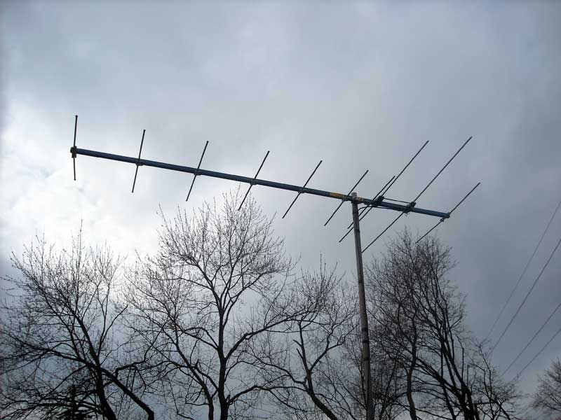
This ten-element Yagi surprised me. Even though the antenna is the wrong polarization and not cut for the Marine Band, the R100 was still able to receive signals from 15-miles away over intervening urban terrain.
Much to my surprise, the em-trak R100 was able to receive AIS signals from a number of vessels passing Detroit. Even working with a considerable disadvantage in antenna, the R100 pulled in three or four vessels in an hour of monitoring. I consider this quite encouraging, and I now plan to install a directional Yagi antenna cut for 162-MHz on the roof to see what it might be able to hear. Stay tuned!
With the AIS receiver connected to my television antenna, the em-trak R100 pulled in a signal from about 15 miles away from the ROBERT S. PIERSON, calling on Great Lakes Steel Corporation's Zug Island plant via the old channel of the Rouge River. I was tempted to drive down to see just how much room was actually left in the channel by this big vessel laying alongside a pier.
With the surprisingly good results obtained with the TV antenna, I have decided to install a dedicated VHF Marine Band Yagi antenna at the house. After conducting a extensive search and careful review of what was available, I settled on a rather unusual antenna. Like the em-trak R100 AIS receiver, the antenna is made in England. I have placed an order for a custom-designed AIS receive antenna, and I expect to have in delivered in about two weeks. I will give more details as soon as I have the antenna on hand.
Since this article was first published, I have installed a much better antenna for the AIS receiver at my home. I am using a custom-designed antenna from InnovAntennas, which I describe in detail in a separate article. I have found reception with this antenna is excellent. On some occasions when a vessel is in the main lobe of the antenna and in certain parts of Lake Erie, I am able to receive their AIS transmissions at distances of over 50-miles. From my location to these vessels the path is mainly over urban terrain, so I am very surprised at the sensitivity of the receiver and the beautiful performance of the antenna. A screen capture (below) shows reception of a vessel in Lake Erie:

The em-trak R100 pulls in a signal using the Innovantennas yagi at a distance of over 50-miles across urban terrain.
The em-trak R100 receiver is, for me, a rather amazing device. It is so small and power efficient that it can be run from a USB connection as the power source. I was very curious to see what was inside. I have to confess, I did not actually disassemble my em-trak R100 to see what was in there, but I asked the manufacturer if they could please send me a view. I was very pleased when em-trak responded with several images showing the internal works of the R100. This saved me from the risk of breaking something when trying to open the case.

The em-trak R100 case opens to reveal the inner workings.
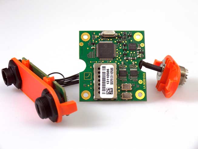
The em-trak R100 is contained primarily on this circuitboard. As far as I know, this is a software-defined radio receiver.
Additional comments and further illustrations appear in an archived discussion thread.
Copyright © 2011 by James W. Hebert. Unauthorized reproduction prohibited!
This is a verified HTML 4.01 document served to you from continuousWave
Author: James W. Hebert
This article first appeared December 3, 2011.
