continuousWave --> Whaler --> Reference
Rescue 21 Radio Installations
by James W. Hebert
This article looks at the Coast Guard RESCUE 21 system, its costs, and its capabilities. Several sites in Michigan are found and described.
Rescue 21
Rescue 21 is the project name for modernization of the radio facilities of the United States Coast Guard (USCG). The USCG describes the system as follows:
Rescue 21 is the Coast Guard’s advanced command, control and direction-finding communications system. Designed to replace the antiquated National Distress and Response System, it provides coverage out to a minimum of 20 nautical miles from shore and is currently active along approximately 42,000 miles of coastline. Rescue 21 more accurately identifies the location of callers in distress via towers that generate lines of bearing to the source of VHF radio transmissions.
For more than a decade, the USCG, through its contractor, General Dynamics, built its vastly improved radio communication system under the project name Rescue 21. The original 1999 proposal for Rescue 21 estimated the cost of its construction and operation to be $250-million. Seven years later, in 2006, the General Accounting Office estimated that the true cost of Rescue 21construction would be at least $872-million. The project was intended to be finished by 2006, but the final handover of the facilities to the USCG from General Dynamics was not accomplished until August 2013, about seven years behind the original schedule. During the construction, some facilities planned for inclusion in Rescue 21 were eliminated and implemented in other systems, perhaps to save costs and speed up the acquisition. A 2012 Government Accounting Office report estimated the true cost of Rescue 21 over its operating lifetime would be $2.66-billion, or more than ten times the original estimate of $250-million. In September 2014, the project lifetime operating cost was again revised upward to be $2.8-billion. A very interesting assessment of the project's costs and benefits is available from the government's IT Dashboard website.
The Rescue 21 upgrade includes improved transmitter and receiver sites with radio-direction-finding antennas. The goal of the system, according General Dynamics (the prime contractor), is to be able to "receive, at minimum, a one second transmission from a one watt power source with an antenna two meters above sea level up to 20 nautical miles from shore." In many instances the radio watch standers are not located at the actual antenna sites. Radio watch is kept mostly at Coast Guard bases, and each Rescue 21 antenna and receiver site is linked to a network. The data-networks carry information about the signals or the digitized versions of the signals themselves. The actual antenna/receiver/transmitter sites became of interest to me in 2013 when, as part of an inquiry into the Nationwide Automatic Identification System (N-AIS), I found that the N-AIS was often locating its base stations at Rescue 21 radio facilities.
Station Sites
The USCG has published low-resolution maps that show the general location of Rescue 21 stations and their predicted coverage areas. Maps for specific segments of the system are available. For example, for the Ninth District–Sector Detroit, a rather good map of Rescue 21 station locations is available. But the map presentation is not sufficient to help one actually locate the station; it may get you within a mile of it, at best. The USCG also seems reluctant to publish a list of their exact locations. (I inquired with the USCG several times about this, and I got the impression that they were not interested in divulging this information to the public.) It is thus ironic that a subset of the Rescue21 stations sites are also being used as the location for stations in the USCG Nationwide Automatic Identification System (N-AIS). These AIS base stations routinely transmit their exact position as part of their AIS transmissions. Indeed, it was from these N-ASI transmissions that I located my first Rescue21 and N-AIS installation.
The complete story of finding my first Rescue 21 site is told in another article, but I can summarize it here: I noticed my AIS receiver was getting AIS signals of an unusual nature, AIS Message Type 4, which is called a "Base Station Report." My chart plotter was not able to decode and display these messages, as it was designed primarily to show only the basic messages sent by ships. This lead me to the discovery of the N-AIS system. By manually decoding the AIS Base Station Report message, I found the latitude and longitude of its source. A visit to that location revealed the installation known to the USCG as RFF WAYNE (Remote Fixed Facility WAYNE).
RFF WAYNE
The Rescue 21 installation at RFF WAYNE consists of an array of several antennas on a leased tower. Considering the cost of the Rescue 21 project, it is very surprising that many of the sites I found were utilizing leased tower space on existing towers, often owned by private operators or by the State of Michigan. Because of the height of most of the towers at Rescue 21 sites, they must be identified by FCC regulations, and typically one finds an FCC registration number. For RFF WAYNE, the tower registration number was 1226906. A search of the FCC tower database found the registration information, and the tower's owner: Subcarrier Communications of New Jersey. The registration also gives interesting details about the tower itself, such as the date of construction and the overall height above ground (in meters).
Antenna Details
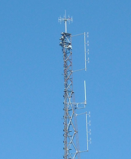
At RFF WAYNE we see a typical Rescue 21 antenna array. Atop the
tower is a nine-element direction-finding receiving antenna. Just below
the direction-finding array are two VHF four-element collinear arrays
used for non-direction-finding VHF reception (usually the upper array)
and transmission (usually the lower array). Between them is a smaller
antenna used for UHF communication.
The direction-finding (DF) antenna array is a key element in the RESCUE 21 system. The nine-element super-resolution VHF DF antenna is believed to be made by Rhode & Schwarz, and the accompanying DF receiver may also be a Rhode & Schwarz product. Such a system is rated to provide reliable reception and direction-finding of signals from a 1-Watt transmitter with a 2-meter antenna height over a line-of-sight range of 30-kilometers. This is almost precisely the specified performance for the RESCUE 21 system (although the USCG rates the distance as 20-miles minimum). The accuracy of the DF bearing to the transmitted signal is rated as 1° RMS. For more about the capabilities of the Rhode & Schwarz DF system, see the their technical literature. I don't know for certain that RESCUE 21 is using the Rhode & Schwarz system, but with the close physical resemblance and the very similar performance specifications, it seems to be a very reasonable inference.
From the FCC tower registration, the overall height above ground of the tower structure at RFF WAYNE is approximately 367-feet. The nine-element DF array is the top-mounted antenna. Using 367-feet as its height gives a radio horizon distance of 27-miles. Using the specified 6.5-feet (2-meter) elevation for the transmitter antenna of the station to be received gives its radio horizon as 3.6-miles. The so-called line-of-sight path distance for the DF antenna array to that 2-meter high transmitter would then be the sum of the two radio horizon distances, or over 30-miles. This exceeds the specified minimum for the Rescue 21 system.
Because of the excellent DF system, the RESCUE 21 system can nearly instantaneously get a radio bearing to any transmitter within 20-miles of one of its radio sites with extremely good accuracy. As coverage of RESCUE 21 sites tends to overlap, it is likely that two (or more) RESCUE 21 DF systems may receive the same transmissions, resulting in two (or more) radio DF bearings. This produces a very good approximate position for the radio transmitter that is originating the signal. Boaters should realize that when they make a VHF Marine Band radio transmission on a channel that is monitored by the USCG's RESCUE 21 system, the position of their transmitter will be immediately known to the USCG with quite good resolution. This capability is something completely new to the USCG radio monitoring service, as prior systems had no direction-finding systems with anything like the speed and resolution of the RESCUE 21 system. A boat making a distress call on Channel 16 is now likely to be shown to be located in an very good approximate position by the direction-finding capabilities of the RESCUE 21 system. Indeed, this greatly enhanced direction-finding ability is a key element of the improved radio system.
The very distinctive appearance of the nine-element DF antenna array also makes identification of a RESCUE 21 remote fixed facility quite simple; if you see that antenna, you are probably looking at a RESCUE 21 site. Visual sighting of the nine-element DF array was 100-percent correlated with finding a Rescue 21 site. The preferred arrangement is to have the direction finding array mounted at the top of the tower, giving it a clear 360-degree radio horizon. When mounted as the topmost antenna, a lightning rod extends above the nine elements of the antenna to provide protection against lightning strikes. When side-mounted lower on a tower, the lightning rod is not necessary. Side-mounting the DF array causes some degradation in direction-finding performance due to the effect of the tower on signals, either blocking them or reflecting them. To prevent signal loss in the transmission line to the DF receiver, very large diameter low-loss coaxial transmission lines are used for the DF array. Two transmission lines appear to be necessary, as direction-finding requires simultaneous comparison of the phase of the arriving signal at two antenna elements of the array.
The two four-element stacked-dipole collinear arrays provide for separate receiving and transmitting antennas. The receive antenna is typically the upper antenna, and a pre-amplifier is provided to increase the sensitivity of the system. The receive antenna can feed several receivers simultaneously. It is believed that six receivers are available, allowing the Coast Guard radio watch stander to be able to simultaneously monitor six channels in the VHF Marine Band for audio traffic. The separate transmitting antenna may provide for uninterrupted monitoring of five other channels while transmitting on one channel. Some information provided by the USCG in environmental impact disclosures indicates that the transmitter power can be as high as 50-Watts.
The smaller single-antenna typically seen is most likely a UHF band antenna, used for communicating with other USCG stations and other government assets on UHF channels.
Transmitter Hut
At the tower base a small equipment building houses the receivers, transmitters, and control system. A stand-by power generator is ready to provide electrical power in case of a utility company power outage. The RFF WAYNE site has a large area enclosed by a perimeter fence, so it was not possible to make close observations of the ground facilities at this location. We turn to another remote fixed facility for those details.
RFF LAKEPORT
After discovering the Rescue 21 facility at RFF WAYNE, my curiosity got the better of me, and I began to hunt for more Rescue 21 sites that were close to me in southeast Michigan. The installation at RFF LAKEPORT was easy to find because, like RFF WAYNE, that site was also being used as an N-AIS station; the precise location of the tower was continually being sent out as part of its AIS message transmission. The location was about ten miles north of Port Huron, Michigan, and inland a few miles from Lake Huron.
Antenna Details
The RFF LAKEPORT site also utilizes leased space on an existing tower, FCC registered site 1001252. The host tower operator is the State of Michigan, and the Rescue 21 system shares space on the tower will several other radio systems. The highest Rescue 21 antenna is again the nine-element DF array, which is side-mounted on the tower at approximately 300-feet above ground (estimated by eye based on overall tower height of 410-feet).

RFF LAKEPORT is located in a rural setting at a short setback from a secondary paved road. The tower structure
is very substantial, as can be judged by comparison to the automobile in the foreground.

The 410-foot tower is difficult to frame in a single photograph. The upper half of the
tower holds the typical Rescue 21 antenna complement: DF array and two four-element
collinear arrays. The collinear antennas are oriented northeast toward Lake Huron.

The smaller UHF antenna is oriented to the South and mounted on a different tower leg.
Transmitter Hut
At the base of the tower a large area is enclosed in a barbed-wire-topped chain-link fence. Inside the fence are two equipment buildings, electrical power distribution panels, a generator, a propane tank, and supports for bringing transmission lines from the tower to the equipment buildings.

The sign on the transmitter hut clearly identifies this location: RFF LAKEPORT. Note the satellite dish antenna
atop the building. It is a very small aperture terminal or VSAT that provides a back up data link to the network.

Five large transmission lines enter the USCG equipment building at Lakeport. The outer conductor of the
transmission lines are bonded to a large earth ground before entering the building structure. This is done
to encourage any lightning strike currents to seek ground before they come into the equipment area.
The presence of five large-diameter coaxial transmission lines is intriguing. Let's assign them each a function. It would seem reasonable that they would connect to antennas as follows:
- VHF transmit four-element collinear array
- VHF receive four-element collinear array
- VHF DF nine-element array primary receiver
- VHF DF nine-element array secondary receiver
- UHF antenna
Using separate receive and transmit antennas would give the installation the ability to feed multiple receivers on various frequencies from the receive antenna, and allow transmitting on various frequencies, one at a time, from the transmit antenna. The direction-finding antenna needs to feed simultaneously two of the nine elements of the array to the direction-finding receiver so it can measure the phase angle between the signals and deduce the heading to the transmitter. This is likely accomplished by a high-speed switching arrangement at the antenna that can pick any two of the nine elements and send them down to the receivers. That accounts for four of the transmission lines, and the fifth is then left for the UHF station. This is just my speculation, but it seems reasonable and based on typical practices in radio communication that I have familiarity with.
More Rescue 21 Facilities Found
Having found the two easy-to-locate Rescue 21 installation due to their transmission of their location in their AIS Base Station messages, I next began to hunt for other facilities. Using the low-resolution USCG coverage maps as a basis, I began to hunt for the Rescue 21 installation at RFF CASCO. The naming convention of Rescue 21 facilities seems to follow local geographic names, and there is a Casco township in the general area where the RFF CASCO tower was shown on the coverage map. On a nice Fall afternoon, I drove up to Casco township and began listening for AIS Base Station signals. I found I could copy five AIS Base stations: Wayne and Lakeport (both already found), as well as three Canadian stations at Sarnia, Leamington, and Grande Pointe. Given the small size of Casco township, I couldn't have been more than six miles away from RFF CASCO, but I never heard a transmission from it. This was the basis for my inference that not all Rescue 21 locations were being integrated with the N-AIS system. Finding RFF Casco was going to take more research.
My first idea was to use GOOGLE EARTH to help in the search, but this was not always possible. Some of the relevant imagery in GOGGLE EARTH (at that time) was from 2008, which might pre-date the construction of the Rescue 21 facilities. Next I used the FCC tower database and set up a search for registered towers that was constrained by geographic boundaries. This gave me a list of possible targets for big towers in Casco Township. On another beautiful Fall afternoon, I went on another road trip, hunting for RFF CASCO. My first hunch was correct, and I found the site not far off from Interstate-94 in a rural setting.
RFF CASCO
RFF CASCO is another instance of a Rescue 21 facilitiy installed on leased tower space. The landlord is again the State of Michigan, per the tower registration information. The tower structure is 125-meters or 410-feet tall. It is located quite a distance from any water, and it covers the northern part of Lake St. Clair and much of the St. Clair River from Algonac to Port Huron. The Rescue 21 antennas are side-mounted at about 325-feet (estimated visually), and consist of the now familiar nine-element DF array, two four-element VHF antennas, and one UHF antenna. The transmitter hut and other facilities are very similar to those already described.

RESCUE 21 site RFF CASCO is located in a rural setting several miles inland from any waterway.
The 410-foot shared tower has plenty of state government microwave antennas and is heavily guyed.

The nine-element DF array is seen very clearly in this telephoto image. Note the red marking
on one element, no doubt used to help the installer align the array.

Three of the five transmission lines appear to be significanly larger than the others.
It is difficult to know which antennas are fed by the lower-loss coax. The cables travel horizontally
under the protection of an overhead bridge, there to keep falling ice from damaging them.
RFF FORESTER
RFF FORESTER, named after the nearby town, is a Rescue 21 site that is not part of the N-AIS system, so it was not sending any AIS Base Station messages with its location. I had to hunt for it. Using the FCC tower registration database, I selected a likely candidate. This turned out to be another good guess. I discovered RFF FORESTER located in the middle of a farmer's field, and the farmer at work harvesting his crop that surrounded the fenced-in tower installation. Again, the Rescue 21 antennas were on leased tower space. This tower is managed by Grain Management. I thought the name "grain" would be associated with farming, but it turns out to just be a coincidence; the last name of founder and head of the company is Grain. Based on their signage, Grain Group appears to manage the site, while the actual tower owner was another firm, accord to the FCC registration data.
The other tenants on this tower are cellular telephone providers, with their antennas installed at about 300-feet. This leaves the top of the tower available for the USCG. With their DF array top-mounted at 400-feet, and the tower just a few miles inland, this Rescue 21 site should have exceptional coverage.

RFF FORESTER is located on a leased tower in a farmer's field, just north of the town of Forester.

The DF Array enjoys the favored top-of-tower mounting, giving it a clear field for direction finding.
RFF HALFWAY CORNERS
RFF HALFWAY CORNERS appears to be named after a highway intersection nearby. Searching GOOGLE for "halfway corners Michigan" got me pointed to the locale. This site is not an N-AIS shared site and doesn't transmit its location. It was found with some good guessing and an FCC database search by geographic boundaries. When the search turned up a State of Michigan tower in the vicinity, I was confident I had found another Rescue 21 site.
From the Forester tower, I drove north about 24-miles to the main highway leading into Harbor Beach. Just east of the intersection of M-142 and Parisville Road, and about eight miles from Lake Huron, RFF HALFWAY CORNERS is located on leased space on a very impressive 500-foot guyed tower. It is hard to miss a structure of this height in flat farmland.
The top of the tower holds a candelabra of communication antennas, and the Rescue 21 DF array is side mounted at about 400-feet, with the two VHF stacked arrays and the UHF antenna below.

RFF HALFWAY CORNERS is located about eight miles inland from Lake Huron on a 500-foot tower.

The DF Array is side mounted, but the system designers must have still considered it at risk for
lightning, hence the lightning rod in the center of the array. The side mount is quite far from the tower,
so the junction box is mounted on the side arm. The large guy brackets prevent the tower from
twisting in high wind loading. Those microwave dishes have very narrow beams and cannot
tolerate any deflection from their aligned heading.
RFF ARCADIA
I visited RFF ARCADIA on a cloudy Fall day in 2016. It is another instance of a Rescue 21 facilitiy installed on leased tower space. The landlord is a private company (SBA GC Towers, LLC ) per the tower registration information. The tower structure is 113-meters or 360-feet tall. The site is several miles from the shoreline of Lake Michigan, in the vicinity of the town of Arcadia, about midway between Manistee and Frankfort. Unlike all prior sites I have visited, this one appears to have only a single tenant, the USCG, and the tower is otherwise devoid of antennas (and income producing tenants for the tower owner). Since the Rescue 21 antennas are the only ones on the tower, they get the optimum locations. The transmitter hut and other facilities are very similar to those already described.

RFF ARCADIA is located about 2.3 miles inland from Lake Michigan on a 360-foot tower.

The nine-element direction-finding array is top-mounted on the tower. The stacked colinear arrays are mounted facing west to the lake. The UHF antenna side mount points north.

The electical utility panel has only one circuit active: U.S. Coast Guard.

The only structure at this location is the transmitter hut for RESCUE 21. The VSAT dish is hidden in this view; it is behind the hut on a pole.
More Rescue 21 Site Locations
As it happens, there are probably more Rescue 21 sites in my home state, Michigan, than in any other. I believe there are 30 installations. I hope to visit in-person more of these sites and document their antenna arrangements, as I have for the six sites already shown above.
My search to discover the location of the other 25 sites was going to be a big task. I received some quite unexpected assistance from another private individual who had similarly been collecting data about RESCUE 21. He shared with me some of his information. As a result of this collaboration, the exact location RESCUE 21 sites on Lakes Superior, Michigan, Huron, and most of Erie are now identififed. These can be located precisely and their approximate range to their radio horizon seen using Google Earth. If you have interest in this information, contact me via email.

Rescue 21 sites in upper Great Lakes and their approximate radio horizons as seen on Google Earth. The .kml file is available; contact the author.
Operational Details of RESCUE 21
The standard procedure of the USCG watchstander is to monitor the direction-finding array on the emergency calling channel, 156.800-MHz or VHF Marine Band Channel-16. The array primary channel cannot be changed. The array has a secondary channel; the normal procedure is to mantain the secondary channel on 157.1-MHz or VHF Marine Band Channel-22A, but it can be tuned to other channels. The direction-finding receiver output is plotted on a display in three ways. A primary line of bearing (LOB) is presented to the operator as a dark red line. A secondary LOB is drawn as a dark blue line. Lines of bearing that are derived from signals that are beyond the radio horizon of the array are drawn with dotted lines, a LOB obtained from over the horizon is drawn with a dotted dark red line. There are three categories of location reports: a single line of bearing (LOB) from the direction finder; a fix solution from the direction finder; and an over-the-horizon fix solution from the direction finder. The Rescue 21 system maintains past data for 30-days; after that the data is archived off-line.
Each site has a total communication capacity as follows:
- the distress channel (156.800-MHz or Ch-16)
- the digital selective calling channel (156.525-MHz or Ch-70)
- two additional VHF voice channels
- one UHF channel
- one VHF data channel (most likely the AIS channels)
- dedicated land-line data circuit (T-1 speed) to USCG network
- a very small aperture terminal or VSAT at selectd sites
The radio watch for digital selective calls is maintained with dedicated receivers and transmitters connected to a VHF DSC modem which decode the frequency-shift-keyed (FSK) audio tones from the receiver. All DSC messages received and decoded are logged and stored on servers. The servers process the call and, if appropriate, generate a digital response, which is sent back to the DSC modems for encoding. The DSC modems then generate the appropriate FSK audio to be transmitted on the DSC channel.
Rescue 21 sites that are shared with the N-AIS may also have additional facilities for receiving and transmitting on the two AIS channels in the VHF Marine Band. Details of those arrangements are not known at this writing.
Each Rescue 21 site has at least one T-1 grade data circuit to provide a connection to the USCG network. If these wired data circuits fail, some sites have automatic back-up roll-over to a 1.2-meter VSAT or very small aperture terminal. The VSAT operates on the Ku-band (12–14 GHz) and links to a geostationary satellite. The satellite downlinks to a central network (DHS OneNet, which itself is a $1-billion project) which then passes the data back to the USCG network for Rescue 21. Apparently failure of the wired T-1 connection or other network outages are the most common cause for a Rescue 21 site to be unavailable. Sites which are deemed difficult to reach for quick service are being provided with the VSAT back-up facilities. About 120 sites were VSAT equipped as of c.2013
I have visited a Coast Guard station with a radio room that is linked into Rescue 21. Unfortunately, I do not have photography or more details of those facilities. I am interested in gathering more information. If any readers have information they can share, please contact me via email.
Equipment Details of RESCUE 21
Based on a recently published solicitation to provide maintenance of Coast Guard RESCUE 21 sites in the Western Rivers, the details of the equipment in use at those sites is now better known than ever before. The Coast Guard described that sector of RESCUE 21 as being "a COTS (Consumer Off The Shelf), Internet Protocol based, P25 compliant LMR (Land Mobile Radio) system with the following main subcomponents:
- Zetron ACOM Common Communications Equipment system version 4.0.29
- Eventide logging recorders
- ICS Electronic V4 Marine Communication System (for Digital Selective Calling and logging)
- NTI Enviromux remote site monitoring system
- Codan MT-E transmitters (4 per tower) and receivers (5 per tower)
- VHF antennas - primarily SD-214 and PD-340 (1 or 2 per tower)
- APC uninterrupted power supply system with external battery pack for emergency power
- Servers and back room equipment to support the Zetron consoles, remote site monitoring system, and DSC are located at two Communications Radio Infrastructure System (CRIS) sites in redundant configurations
- All dispatch consoles and remote radio sites are connected through the CG OneNet network."
This solictation was for certain sites (called "modified version" sites) in the Western Rivers, and the Coast Guard has noted, that
Due to the geographic and operational nature of the western rivers region, the modified system design will not include direction-finding or digital selective calling. The modified system comprises new remote radio control console systems and new VHF FM radios for the three sectors of the western rivers region.
These Western Rivers sites are different from the usual coastal sites, such as the ones described in this article for the Great Lakes coastline, which all have have RDF capabilities, however, I would hope that much of the other gear is quite similar among all sites.
The Coast Guard acknowledged in a public document that the direction-finding and digital selective calling sub-systems will remain proprietary to General Dynamics, and they (apparently) will get a exclusive contract for their maintenance and service.
Summary
Of the six sites described above and personally visited, the Rescue 21 facilities at WAYNE and LAKEPORT were simple to locate as they transmitted their exact position in their AIS Base Station messages. The sites at CASCO, FORESTER, and HALFWAY CORNERS were not participating in the Nationwide Automatic Identification System (N-AIS) and did not transmit their location. They were found with a combination of geographic searching using the FCC registered tower data base, guided by the USCG coverage maps, and some good guessing. RFF ARCADIA was located with the more recently discovered information on all sites in the Great Lakes.
Since I began this project, the popular website MARINETRAFFIC.COM has improved its presentation of AIS data to include AIS Base Station transmissions, and, as a result, it now maps the position of all Rescue 21 sites in its coverage area that are transmitting their own position as part of N-AIS. This makes it simple to locate these sites, as you no longer need to have your own AIS receiver to decode and plot these position. Based on what has been observed in southeast Michigan, it looks like there will be at least one and perhaps two Rescue 21 sites not sending any N-AIS data spaced between the Rescue 21 sites that are revealing themselves with N-AIS transmissions.
If readers would like to inquire further on this topic, a thread exists on the SMALL BOAT ELECTRICAL forum to receive your comments or questions.
Copyright © 2016 by James W. Hebert. Unauthorized reproduction prohibited!
This is a verified HTML 4.0 document served to you from continuousWave
Author: James W. Hebert
This article first appeared February 29, 2016.

