continuousWave --> Whaler --> Reference
VHF Marine Band Antennas For Small Boats
by James W. Hebert
The range of communications using a VHF Marine Band radio is primarily determined by the antenna installation. This article explores an optimum configuration for a small recreational boat.
Choosing a VHF Marine Radio Antennas
Practically all recreational small boat installations use commercially manufactured antennas. There are several brands in very wide distribution, and
choice of an antenna is often made from the selections offered by these manufacturers. For installation on my 22-foot Boston Whaler boat, I did not find any of the more commonly used antennas to be appropriate, and I searched for a better solution. The primary goal of my search was to find a way to increase the overall antenna height above the water. In a previous article, I demonstrated that the antenna height has the greatest impact on the communication range of the radio. Getting the antenna as high as possible was the most important factor.
The size, weight, and cost of the antenna were also considered. The boat's current antenna mounting hardware should be re-used, if possible, and the cost of the antenna must not be excessive. Because the boat can be operated at speeds of over 40-MPH on the water, and, if the antenna is accidently left in the upright position when on the trailer, at speeds of over 60-MPH on the highway, the wind loading of the antenna should also be minimized. The appearance is also moderately important. Finally, the electrical performance was paramount. The antenna must be an efficient radiator.
Higher Mounting
Many small boats are equipped with a radar arch, even if they lack any RADAR facilities. The arch makes a great place to install the mounting base for an antenna. It elevates the antenna base to about 7-feet above the water. Unfortunately, my boat does not have a radar arch, and for many reasons I probably will not install one. My antenna will have to be mounted elsewhere.
The current mounting location is at the base of the cabin superstructure on the starboard side. This location is just forward of the helm. It allows the helmsman to easily reach over the windshield to operate the tilting ratchet to lower the antenna. If at all possible, it was very desirable to re-use this location. Doing so would avoid having to make repairs to the hull (by filling the four 1/4-inch mounting holes), and the location had proven itself to be a very practical spot for an antenna.
What Was Wrong With My Old Antenna
As originally equipped, my boat had a very common eight-foot fiberglass tapered whip antenna. This is a so-called 6-dB gain antenna. The actual active part of the antenna is the upper 7-feet or so; this is where the radio frequency energy radiates from the antenna. This was precisely part of the problem to be cured. The antenna is just a foot removed from the helm dashboard panel which contains a number of instruments, including the engine tachometer. Whenever the radio transmitter was keyed, so much radio-frequency energy was emitted from the base of the antenna that the tachometer gauge was affected. The indicator pointer on the tachometer would swing upward whenever the Push-to-Talk (PTT) button was pressed. This was a clear sign of interference from the antenna. Also, it demonstrated how some of the transmitter's power was being radiated from the base of the antenna, only one-foot up from the mounting.
The 8-foot fiberglass encased antenna had another problem: durability. The fiberglass tube radome for the antenna is prone to breaking if the antenna happens to hit an overhead obstruction. This seems to occur most often with trailer boats when the antenna is not lowered before highway travel. The fiberglass radome also tends to decay with long-term exposure to sunlight, and it may start to shed little bits of the cloth fiber. The antenna is also more prone to damage when is is a tilted-down position and might be stepped on accidently.
The search for a new antenna was focused on finding a four-foot antenna which could be mounted to a four-foot base extension installed on the original mount. This would put the average height of the antenna at 6-feet above the base, or at 10-feet above the water. This would increase the average antenna height by 1.5 feet above the water. While this does not sound like a huge increase, it will translate into greater range. Any improvement in antenna height is likley to make an improvement in range of radio communication. (For a more formal analysis of this behavior, please see "VHF Radio Propagation Over Water", an article I recently wrote that demonstrates the significance of increase in antenna height on signal strength.)
The Ideal Three or Four-foot Antenna
The search for the ideal four-foot antenna proved to be difficult. There were many common four-foot antennas made with construction similar to the original antenna using a tapered fiberglass whip. However, most of these were too heavy to be supported by the original mount when placed atop a four-foot extension mast. They also had significantly more wind area, as well as significantly higher cost. For these reasons, the fiberglass whip with molded-in base style of antenna was eliminated from consideration.
The ideal antenna construction appeared to be one using a small diameter steel whip in conjunction with a base loading and matching coil. There were several choices of manufacturer for this style. Most of these antennas were intended for mounting on the top of sailboat masts, and they did not have a threaded coupling which would screw onto a standard mast extension. Some had adapters for this purpose, but they were judged to be awkward or a kludge. One antenna from a common manufacturer had all of the desired attributes, but its base coil was extremely large. This was both a size and aesthetic problem.
The GAM ELECTRONICS Antenna
Finally, after exploring many websites and GOOGLE search results, the ideal antenna was found. A small manufacturer in New Hampshire, GAM Electronics, had the perfect solution. Their model SS-2 was exactly what I was looking for. It was a little over three-feet long, and in conjunction with a special mounting accessory model ADAP-II, it can be threaded onto the end of a standard extension mast. Mechanically, the SS-2 was exactly what I wanted. But what about its electrical properties?
I called GAM Electronics and spoke directly with Ed, the company owner. He told me about his product and proudly boasted that every antenna was hand tuned and tested during assembly! He also pointed me to an independent test of his antenna among a group of many popular antennas. The results were very impressive. The little SS-2 produced better signals than many much larger and more expensive antennas in actual field strength tests. And the VSWR was a very low 1.24:1. Electrically the antenna looked to be a better performer than most garden-variety 8-foot fiberglass whips. The antenna uses military grade RG-58C/U coaxial transmission line, too, which I strongly prefer over so-called "marine grade" cables.
The mechanical design is also quite optimum for a small boat. By separating the whip, the coil, and the mounting adapter into three components, the replacement of the antenna is modular. If the whip breaks--which is unlikely given its stainless steel construction--you need only replace the whip portion. If the coil breaks, just the coil can be replaced. You won't have to run all new feed line because that is part of the ADAP-II mounting.
The GAM Electronics SS-2 is a popular choice for an antenna by Boston Whaler Commercial and Government Products. Ed informed me that Whaler was a long-time customer of his. And, of course, with a name like GAM Electronics, what could be more appropriate for a Boston Whaler boat!
Update: I notice that Gam Electronics now refers to a model SS-2 Marine, an new designator. This antenna may be ordered for use with marine radios. The antenna is pre-tuned for best performance on the VHF Marine Band at 156.875-MHz. (But I wouldn't forgo the standard or untuned model if available at a much better price. With the standard antenna, you will be cutting the metal whip radiating element to length from a chart. It is a simple procedure and easily done.)
Installation
In early April I ordered a GAM SS-2 and ADAP-II mount. The antenna arrived a few days later. As soon as I took it out of the box I liked the look and feel of the little whip and coil. Its weight and wind loading would be about as light and small as one could hope for. Actual installation on the boat took longer than expected. It was mid-June before I had the new antenna installed. I mounted it atop a Shakespeare 498 four-foot white polycarbonate extension mast, using the original tilting base mount. I snaked the feed line down the extension mast, through the mount, and into the cabin. I soldered on a PL-259 connector (not supplied) and hooked it to my VHF Marine Band radio.
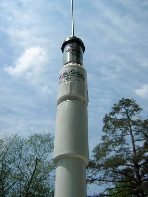 |
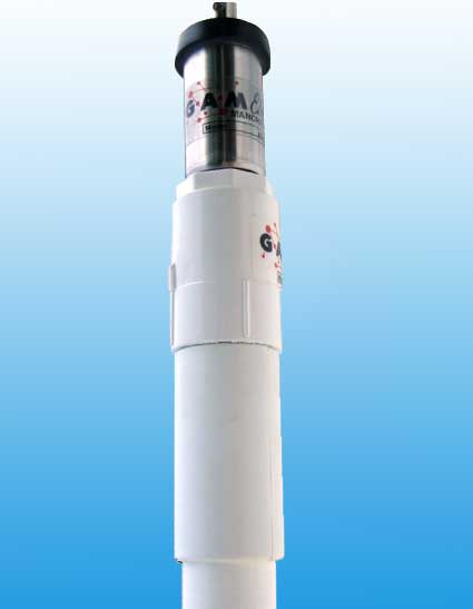
GAM Electronics SS-2 Antenna; ADAP-II Base
The GAM Electronics SS-2 antenna screws into the ADAP-II base.
The base in turn screws into a standard Shakespeare 498 four-foot extension mast. Relatively small size of the base loading/matching coil reduces the weight and wind loading. The stainless steel whip can be easily replaced or pruned for optimum resonant frequency. The coaxial cable feed line is integral with the ADAP-II base, and it is routed down the extension mast to the base.
Photo Credit: James W. Hebert |
Sitting in my front yard about 22-miles from the Detroit River, I began to hear all of the commercial vessel traffic coming in loud and clear. I also could get good reception on Vessel Traffic Control up in Sarnia, Ontario, about 65 miles to the northeast. The little antenna was working well on receive.
Mechanically, however, I was worried. The total weight of the antenna and mast was probably greater than the original 8-foot whip, and the plastic extension mast was definitely stiffer and had more wind area. Moving the extension mast slightly produced some flexing in the cabin side, and this did not look like a good long-term situation. It could lead to problems in the laminate strength. I explored the back side of the mount. I found that the 1/4-inch mounting bolts were only retained by small washers and elastic stop nuts; there was no reinforcement. A backing plate was deemed necessary.
|
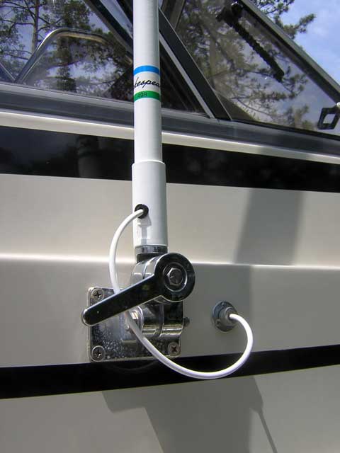
Shakespeare 498 Extension Mast and Base
The Shakespeare 498 plastic four-foot extension mast is an inexpensive ($30) way to raise the antenna. The mast threads onto the existing stainless steel ratchet mount. To reinforce the mount, a 4-inch by 6-inch backing plate was fabricated from 1/4-inch thick aluminum plate.
Photo Credit: James W. Hebert |
A backing plate of about 4 x 6 inches was fabricated from a piece of scrap aluminum. Taking careful measurement of the hole layout of the existing mount, the four holes were laid out and drilled on the backing plate. The mounting screws were then slowly removed, until the antenna mount base was left in position, retained only by the adhesive sealant used to bed it to the hull. The sealant supported the entire weight of the mount and antenna! The backing plate was placed in position, and the four bolts re-installed and tightened. The whole operation had to be done by feel, as there is very limited visual access to the cabin interior where the antenna mounting bolts fasten. My hole layout was very good, and all four bolts fit perfectly into the backing plate holes, which were drilled only 1/16-inch oversize.
Performance
We just finished our first long weekend aboard the boat with the new antenna. So far the antenna appears to be working as expected. Our reception seemed on par with the two other boats in our company whose 8-foot antennas are mounted to bases on their radar arches elevated about seven feet above the cockpit deck. While siting at the main dock in Leland, Michigan, we were able to receive the NOAA weather radio station from Wisconsin (most likely WXN-69, Door County, 162.425 MHz), coming in from across the lake at a range of approximately 60 miles. (A chart of the expected coverage area of WXN-69 shows that Leland is beyond their normal receive range.) In prior comparisons like this, these boats had always shown greater radio range. We have yet to make any meaningful measurements of transmission range. These will come in the future. As expected, operating the transmitter no longer produced any interference with the tachometer. The antenna is now several feet above the instrument cluster. I also anticipate the antenna will perform better on transmit because now all of the power is being directed into the upper portion of the antenna; none is wasted by radiating into the helm console.
The mechanical performance of the antenna was good. It did not have as much movement as I expected, and instead, when running at speed, the wind pressure seemed to steady the antenna. It does not look like there will be long-term mechanical effects from the slightly heavier antenna.
|
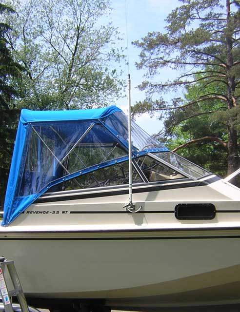
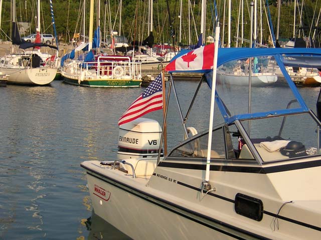
Boston Whaler and GAM Antenna
The actual antenna is now elevated well above the helm and its instruments and electronics. The extension mast creates a handy signal staff for flying of courtesy flags when in foreign water or for small pennants. (This photo was taken in 2006. In 2017 the large pine tree in the background died and was cut down. The GAM SS-2 antenna continues to operate as it did in 2006.)
Photo Credit: James W. Hebert |
VSWR Measurements
I made the following VSWR and POWER Measurements for the SS-2 Antenna:
GAM Electronics SS-2 VHF Marine Band Antenna
Transmitter: ICOM M-402
Directional Wattmeter: DAIWA CN-620
July 16, 2006
Vessel CONTINUOUSWAVE on its trailer
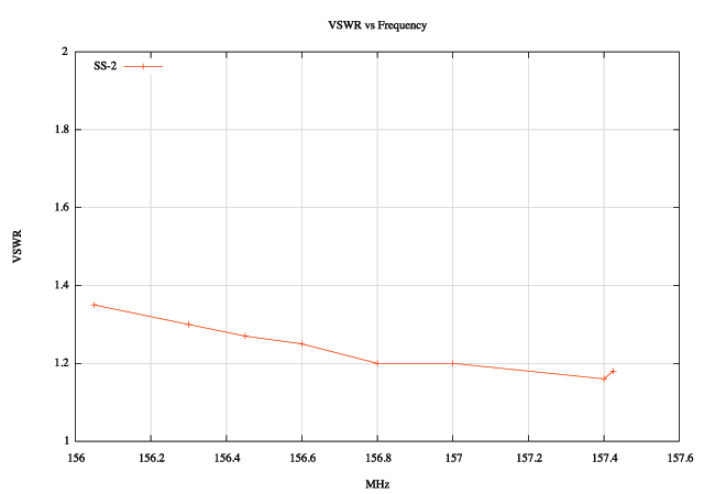
FORWARD POWER and VSWR versus FREQUENCY
CHANNEL MHZ WATTS VSWR
01A 156.05 18.5 1.35
06 156.3 18 1.3
09 156.45 18 1.27
12 156.6 18 1.25
16 156.8 18 1.2
20 157.0 18 1.2
28 157.4 18 1.16
88 157.425 18 1.18
The VSWR looks very good. This in itself is not a measure of the antenna's effectiveness, but an effective antenna will have a low VSWR and proper match to its feedline. The GAM Electronics SS-2 shows these qualities across the VHF Marine Band.
Unanticipated Benefit
One unforeseen benefit of the new installation is the extension mast itself. It makes a perfect location for flying a courtesy flag when visiting Canada, which we often do. Because the mast is definitely not part of the actual antenna, there is no electrical or esthetic problem in attaching a small flag to it.
Installation Details
As shown above in the close up photograph, the stock Shakespeare 498 extension mast does not quite completely thread into the GAM ELECTRONICS ADAP-II base. To get a cleaner installation it is recommended (first suggested by Seth Campbell) that approximately four threads be cut off of the top of the Shakespeare 498 extension mast threaded fitting. This will allow the ADAP-II base to thread completely onto the extension mast. Also, there is a stainless steel mounting nut supplied with the SS-2 antenna. This should be removed before threading the antenna onto ADAP-II mount. This nut is used when the antenna is mounted on a different type of mount and is not needed with the ADAP-II base. Recently GAM ELETRONICS began to offer the ADAP-II mount in a black version. Be certain to specify the color your prefer when you order one.
|
Shakespeare 498 Mount
From top to bottom: GAM SS-2 antenna, GAM ADAP-II mount, Shakespeare 498 extension mast. To get a cleaner installation the plastic threaded coupling on the 498 extension mast has been trimmed by about four threads.
Photo Credit: Seth Campbell |
|
Courtesy Flag Staff
The four-foot extension mast used to raise and support the GAM SS-2 antenna also makes a perfect staff for flying a courtesy flag when cruising in foreign waters. The United States Power Squadron recommendations concur. Here is CONTINUOUSWAVE at a transient berth in Lions Head, Georgian Bay, Ontario, Canada.
Photo Credit: Christine Wilson |
Follow-up
The 2019 boating season will be my 13th year using the GAM Electronics antenna and mounting system described above. All the original components of the system are still in use and working perfectly. The performance of this antenna system has been excellent. I can routinely communicate with any other boat or shore station that I can receive. On open water it is typical to communicate boat-to-boat at 15-miles or more. On receiving the antenna has been fabulous. I have good signals from NOAA weather broadcast transmissions at ranges of over 75-miles. I continue to strongly endorse this antenna installation for use on small boats.
UPDATE 2019: the 13th year was an unlucky year for the GAM SS-2 antenna. The antenna transformer or matching coil component had a mechanical failure, which lead to an electrical failure. The transformer assembly consists of an SO-239 jack at the base, a cylindrical steel housing attached to the SO-239 jack, and a non-conducting upper cap, through which the antenna ferule for connecting the whip radiator is located. The adhesive at the press-fit joint of the insulating cap to the steel cylinder failed. With the cap loosely fit on the cylinder, motion from the whip was transmitted to the internal coil and connections inside the cylinder, resulting in fatigue and failure of the connections.
In my particular installation, antenna and supporting mast spend most of the time—all but perhaps 50-hours per year—in a horizontal position. This puts a bending moment on the transformer coil assemby from the weight of the whip hanging off it. Also, the boat is often trailered at highway speeds, where the whip tends to oscillate in the 55 to 65-MPH or higher wind. I believe this chronic exposure to sideways loading on the cylinder-cap joint contributed to the failure.
As mentioned above, the modular nature of the GAM SS-2 antenna permitted a repair by just replacing the transformer assembly. The repair required about two minutes and consisted of unthreading the old transformer, removing the whip, installing the whip on the new transformer, and threading the new transformer onto the ADAP-II base.
UPDATE 2023: Sometime after Yankee Microwave took over manufacturing the GAM antennas and mounting accessories, the design of the ADAP=II mounting adaptor was significantly changed. The newer ADAP-II mounting adaptor relied on press-fit of the antenna can into the adaptor, whereas the prior model used a threaded fit. GAM Electronics has now introduced a better mounting adaptor to replace the ADAP-II. The new adaptor is made from stainless steel. It is sold in a bundle with the SS-2 antenna, the new adaptor, and RG-58C/U transmission line for $127.55. (That price is only $10 more than buying the plastic ADAP-II mount, antenna, and transmission line separately.) More details in another recent article in the forum.
Tilting Base
As shown above, the GAM antenna and mount and the extension mast are threaded onto a tilting base. This tilting base was already installed on my boat, so I retained it for the new antanna. However, as I memtion above, I added a 1/4-inch-thick aluminum backing plate to better spread the forces from the antenna and mast onto the cabin superstructure, where the base is attached to the hull. If your boat does not already have a tilting mount installed, I recommend using a good one, such as the Shakespeare 4187 or Shakespeare 4187-HD stainless steel ratchet mount antenna base. They are a very strong base and available for about $50 to $55. The tilting mount is very useful for a trailered boat, as it permits the antenna to be lowered for highway travel at high speeds.
Costs
When I assembled the components used in this antenna for my installation in 2006, the total cost was around $100. Prices have increased somewhat since then. Thirteen years later in 2019 the GAM SS-2 antenna now has an MSRP of $80 but is typically available from DEFENDER.COM for $55. The ADAP-II mount adaptor is also available at modest discount at DEFENDER.COM for $27. The total antenna costs are now about $82.
Finding Four-foot Extension Masts
The Shakespeare 498 extension mast had a list price is $81, but it was available c.2015 from DEFENDER.COM for $40, although that was noted as a closeout sale. As of June 2016 the Shakespeare 498 extension mast was no longer being made. Look for old stock or chose an alternative, such as more expensive Shakespeare 4008-4 extension mast, now about $60 to $90 at retailers. The cost increase for an extension mast has driven up the total cost of the recommended antenna system, but I still prefer this arrangment.
Another option: make your own light-duty 4-foot mast from PVC pipe and pipe fittings. Visit a good hardware or plumbing supply for the parts. For security, use mechanical fasteners and the usual PVC glue. Costs should be under $10.
Coaxial Connector
Because there is no connector provided, a suitable PL-259 type connector will need to be installed. You can buy PL-259-type connectors from marine suppliers. To use a PL-259-type connector with the RG-58C/U cable from the GAM ADAP-II, you will need a reducer. The reducer is known as a UG-175. You can find both the PL-259 and UG-175 sold as a bundle for $3 at electronic suppliers.
For an unusual recommendation for a suitable connector, please see my article on For Mobile Equipment or FME connectors. An FME connector and PL-259 adaptor will together cost about $7 from a major distributor. The FME connectors will require a crimp tool for proper installation. A nice crimp tool will cost about $33.
Questions or Comments
Questions for the author or comments about this article may be added to the discussion reserved for that purpose.
Copyright © 2004 by James W. Hebert. Unauthorized reproduction prohibited!
This is a verified HTML 4.01 document served to you from continuousWave
Author: James W. Hebert
This article first appeared July 10, 2006. In 2016 and 2018 I revised some portions and hyperlinked resources to better reflect current prices and availability at vendors.

