
Side Mount Controls, 13-foot and 15-foot Limited Models

In most cases, the dealer will have installed your outboard motor following all the prescribed practices by Boston Whaler and the engine manufacturer. Should you be making the installation yourself, the following is a guide.
On all models, outboard engines should be clamped directly onto the transom. On 9, 11, and 13-foot models used as tenders where low horsepower engine may be removed frequently, some elect to install an aluminum plate on the transom interior. The use of Rubber transom protectors is discouraged as they may ride up on the smooth gelcoat surface causing potential loss of the engine.
The transom core is solid plywood with a thick layer of fiberglass on the inside and out. Engines, when clamped tightly, will bite into this fiberglass, providing good holding for the engine. Engine clamps should be checked and retightened frequently, especially during the first several hours of operation.
11, 13, 15, and 17-foot models, with higher horsepower engines, require engines to be bolted onto the transom in addition to clamping. This is no problem as in most cases the engine splash well is sufficiently deep. 17-foot models with larger engines containing deeper mounting brackets will not be able to use the normal lower bolt holes. Most engine manufacturers provide an upper optional hole or a blind threaded hole in the engine bracket lower hole group. Check with your Boston Whaler or Engine dealer.
On 13-foot models (prior to 1986) the transom is slightly curved. If on larger, newer engines there is a space between the engine and the transom, washers can be used to fill the space to prevent bending or placing too much pressure on the engine bracket when the bolts are tightened up. 13-foot models after 1986 have a flat raised area on the transom for engine mounting.
The engine tilt pin adjustment influences both the boat's handling and riding characteristics as well as steering loads.

On boats not equipped with power tilt and trim, the tilt pin should be set so the cavitation plate of the engine is parallel with the bottom of the boat. When the engine is moved closer to the transom, it will depress the bow, making the boat slower. When moving the tilt pin away from the transom, the bow will become lighter, increasing performance and engine efficiency. You will have to experiment with tilt pin adjustment to optimize the setting based on your boat and normal load conditions
All higher horsepower engines are equipped with power trim and tilt. The trim control is usually built into the engine control handle or mounted as a separate switch on the console dash panel. Power trim adjusts the engine angle to compensate for changing load and sea conditions. However, improper use of power trim will affect engine efficiency, steering pull, and bow light/bow heavy running characteristics.
On larger Outboard motors, there is a steering trim tab located on the bottom of the cavitation plate, just aft of the propeller. It is adjustable and has been installed on the engine to correct for propeller torque.
Adjustment of the trim tab should be done after you've gone through the steps of proper tilt adjustment.
The boat should be operated with a normal load on board in a straight line. Incorrect trim tab adjustment will cause the boat to turn to the left or to the right when your hand are removed from the steering wheel. Be careful when removing your hands from the steering wheel; a tilt tab incorrectly positioned may cause the boat to turn violently.
To adjust the trim tab, loosen the securing bolts, as per the engine manufacturer's instructions, and move the trim tab in the direction the boat pulls. For example, if the boat pulls to starboard, move the trailing edge of the trim tab to starboard. Make these adjustments in small increments and test the results. The object is to create a "hands off straight line" steering condition for the normal operating speed. It is not possible to eliminate steering pull throughout the engine speed range.
Remember, tilt adjustment may affect steering torque as much as the trim tab. With Outboard engines equipped with power trim this becomes particularly important. When under way, experiment with trim settings to neutralize steering pull.
Most 9 to 17-foot models ride best with weight positioned from mid-ship aft. Sitting on the bow locker area while underway or then the boat is on plane is not recommended. Weight in this area will cause the boat to "plow" through the water at less than planing speeds, and on plane the bow area is the roughest riding position on any boat. CAUTION: Do install optional bow deck cushions on any boat which is not equipped with a bow rail.
Weight on these models should be balanced evenly between the rear platform and the thwart seat. When loading gear, it should be kept low in the boat to lower the center of gravity. Rowing the 9-foot tender can be done from either the forward or middle oar lock position depending on load balance.
When using small horsepower engines, weight should be balanced between the center thwart seat and rear platform. On sport models, with 15 to 20 horsepower engines, weight, including passenger and fuel tanks, should be moved aft for best performance. The 11-foot Super Sport model has room behind the seat back for battery and fuel tank storage.
All 13-foot models should have weight aft during high speed operation. In choppy water, when running slow, shift weight to obtain a comfortable ride based on sea conditions. Too much weight forward will result in spray coming aboard. Too much weight aft may reduce spray but result in an uncomfortable ride. Adjust speed and weight so the boat is nearly level. When operating into a strong head wind move weight forward to reduce bow feathering and the possibility of becoming air borne. When running alone into a chop or head wind, adjust the tilt pin one notch closer to the transom to keep the bow down.
All 15 Whalers have a sharper bow entry resulting in a softer ride in chop conditions. Weight should be aft or in the middle of the boat for best ride at higher speeds. Because of a redefinition of horsepower by engine manufacturers, your 15 Whaler is a high performance boat when equipped with the maximum 70-HP engine. Any operator should be properly trained for the use of a high performance boat. When running alone at high speed DO NOT trim the engine too far out from the transom or dangerous chine walking conditions (side to side rhythmic motion) could result. Moving your passengers forward to the thwart seat will result in better performance. NEVER TAKE YOUR BOAT TO THE POINT WHERE YOU DO NOT FEEL IN CONTROL.
All Whaler 17-foot models should be run with the bow light and high for a comfortable ride. This trim will produce faster and more efficient engine speeds. 17-foot models are affected by weight trim. To raise the bow, move passengers aft, adjust engine trim further away from the transom, or slow down. In a crosswind, the boat may lean to windward with consequent wetness. Shift weight accordingly to compensate. With high horsepower engines which create considerable propeller torque, it is not unusual to have a slight port list at planing speeds. Compensate with a passenger on the starboard side of the Montauk model. Mounting a transducer or 6-inch fixed trim tab on the port side will also improve the hull trim and counteract propeller torque.
To judge performance of your boat/engine combination, a tachometer is necessary. These are available from the engine manufacturer or are available as part of Boston Whaler's optional instrument panel. Some dealers are equipped with portable units, and all dealers should "Tach-Out" a new engine installation to make sure engine and boat are performing satisfactorily.
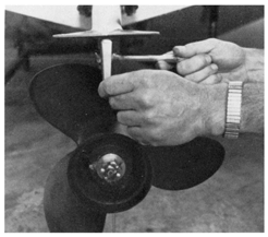
When selecting the correct propeller, tell your dealer what type of boating you will be doing. Will you be carrying a heavy load or light load? Do you need acceleration for water skiing or top speed with light loads? These are important factors for proper propeller selection.

The correct propeller diameter and pitch should permit the engine to attain maximum rated RPM with the anticipated load. The engine owner's manual will tell you the minimum and maximum operating RPM. Do not choose propellers which will allow the engine to exceed the maximum RPM.
The correct propeller will not only give you good performance but will save you fuel and reduce engine wear as well.
(Wire rope) cable and pulley steering is used on the Sport 11. We have used this dependable system for many years on 13-foot models. All earlier 13-foot Sport models are equipped with (wire rope) cable and pulley steering. As outboard engine manufacturers have made through-tilt tube steering available on lower horsepower engines, we have equipped newer (1981 and later) 13-foot models with mechanical steering. All 11- and 13-foot models, whether equipped with (wire rope) cable and pulley steering or mechanical steering systems, need periodic adjustment and replacement of components to avoid unexpected loss of steering.

These boats are equipped with a single large steering spring on the starboard side of the engine. DO NOT install a spring on the port side as unexpected over steering could occur. On 11-foot models the spring should be adjusted to half its length with the engine in its normal running position. This will give satisfactory steering response. On 13-foot models with 20-inch transoms the spring should be compressed to three-quarters its normal length. When the engien is tilted up the spring will relax, absorbing the excess cable. If proper tension is not maintained, the cabe will loosen and come off the grooved steerer drum.
The tiller cable has a nylon covering over a stainless core. Tiller cable should be checked on a regular basis for any cracking of the nylon covering which will allow water to enter causing corrosion of the cable and ultimate cable failure. Any worn spots on the nylon cover would also indicate replacement is necessary. Replacement cable can be obtained from your Boston Whaler dealer. Do not use cable with a vinyl cover as it wil not stand up in use.
Pulleys should be lubricated periodically, using graphite, marine grease, or 30-weight oil. This will ensure they continue to work freely and prevent cable wear. Pulley pins (see diagram) should also be inspected for wear and replaced if wear is noted.

All 13, 15, and 17-foot models are equipped with mechanical steering. In most cases your Boston Whaler dealer will have connected your steering to the engine using the appropriate drag link and the steering cable will be secured through the engine tilt tube in accordance with the steerer manufacturer's instructions. For further information on installation refer to the steerer manufacturer's instructions provided in your owner's package.
Mechanical stering cables are a vinyl jacketed steel core material. Any cracks or abrasion in the vinyl jacket will cause swelling of the core and result in hard steering. Therefore, if any cracks or abrasions are noted on period inspection, the cable should be replaced. If any change is steering or steering loads occur, check with your dealer immediately. Remember, steering is critical to your safe operation of the boat at any speed.
On 11, 13, 15, Sport, Super Sport, and all Limited models standard engine manufacturer's side mounted controls should be installed on the mahogany seat hold down board or fiberglass side panel on Limited Models. These controls are equipped with a starter safety switch which prevents starting the engine in gear. The control must be in the neutral position to start. This is an important safety feature. Should the boat start in gear, have your Boston Whaler dealer check out the control.

Side Mount Controls, 13-foot and 15-foot Limited Models

Binnacle or Top Mounted Controls
On the 17 Super Sport, side mounted controls can be installed on the vertical panel just to the right of the steering wheel. It is also possible to install a single lever binnacle (top-mount) control on top of the console. We offer this type of control with tilt and trim built into the control handle or the standard Morse single lever control with a separate trim switch mounted on the console dash.
Striper 15, Striper 17, Newport 17, and Montauk 17 models must be equipped with a binnacle mount (top-mount) control. We offer both the Morse single lever control and Morse single lever control with tilt and trim in the handle as a control option.
Control cables are plastic jacketed. You should ensure that all bends are gradual (5-inch radius minimum) and that there are [no] cuts or worn spots in the cable jacket. Tight bends will result in stiff operation of the controls. A break in the cable jacket will result in cable failure. Cables should be checked every time you use your boat, if any abnormality exist, have the control system inspected by a dealer.
As a general rule, batteries on Boston Whaler boats should be located aft for best weight trim. This is also the softest riding portion of the boat where there is less danger of the battery bouncing, being damaged, or spilling acid.
Provision has been made on all Boston Whaler for the installation of batteries and VRO tanks. This is in the form of a special wood pad molded under the fiberglass floor to accept the screw fastenings of the battery hold downs. Represented below are installations, consult your wood locating diagram (included in Owner's package with boat) for exact location of the wood mounting.
Mounting the battery hold down or VRO tank where they do not secure into wood will result in fastenings tearing through the fiberglass.
Batteries should always be enclosed in covered battery boxes as shown. Some VRO tanks will also fit into battery boxes. It is important that a battery hold-down strap prevent the battery and battery box from moving to avoid wear on the gelcoat surface. We recommend the use of our battery box and heavy-duty, toggled, hold-down strap.
On the 9-foot Tender no provision for battery mounting has been made. These models are equipped with low horsepower engines which do not have electric start features. Their general use as dingies rarely requires navigation lights. If lights are necessary, you will find the use of portable clamp-on flash light operated lights easier than equipping these models with permanently installed batteries.

11-foot Models should have the battery located on the port rear floor just forward of the molded-in stern seat—check your wood locating diagram. The 11 Super Sport has wood molded in the rear floor just behind the thwart seat and seat back for battery installation.

13-foot Models have wood molded in the boat directly forward of the rear drain sump. The battery should be mounted with its long axis athwartship to provide room for a 6-gallon tank on either side. If engine is equipped with a VRO tank, the tank should be mounted on the starboard rear floor. In this case, only one 6-gallon tank will fit.

15-foot Models have full floor wood [after stencil number 5A0857] so battery and VRO tank placement can be flexible. Most elect to place the battery with its long axis fore and aft just to starboard of the offset rear drain sump. Mounted in this position, there is room for 6-gallon fuel tanks on either side. On the 15 Striper model, batteries are best placed on the port floor behind the optional rear pedestal seat. VRO tank can be mounted on the rear floor or inside the storage box on Super Sport models.

17-foot Models also are equipped with full floor wood which provides flexibility in battery and VRO tank placement. Most elect to place the battery on the port rear floor where it is close to the terminal block and stern light. This shortens wiring runs. Some elect to place the battery on or just forward of the wooden sump cover. This is also a good location as it is on the center line of the boat and will not affect hull trim at rest. On the Montauk 17 some have elected to install batteries inside the console. We are not in favor of this location as it complicates the rigging, is hard to service the battery, and unless the floor of the console is reinforced, can damage the console floor. More importantly, all batteries give off gas which could be explosive under certain conditions and gases shorten the life of electrical wiring connectors inside the console. VRO tanks can be placed inside the console on Montauk models, placed on the rear floor, or, on Super Sport and Limited models, in the storage box.
On the Newport 17, equipped with the optional stern deck, there is room under the deck to mount the battery on the port rear floor.
An auxiliary engine will not give 9-foot—17-foot boats sufficient power to plane. It will provide emergency back-up power should the main engine fail. Auxiliary engines should be equipped with a low pitch propeller to provide operating performance of about six to ten miles per hour.
With the auxiliary engine mounted off center and its limited power, use in heavy sea conditions can be difficult. We do not recommend the complication of attempting to mount a tie bar and separate controls for the auxiliary engine. For close manuevering around docks it is easier to step to the stern and control steering, throttle, and shifting of the auxiliary engine.
During rough running with the auxiliary engine up, you may want to lock the engine in the up position to prevent it from inadvertently bouncing out of its tilt lock and dropping down.

All 13's with 20-inch transoms have wood molded into the port side of the transom for clamping auxiliary engines directly on to the transom. Some earlier 13's are also equipped with these features. Check your wood diagram or the factory for the exact location. The auxiliary engine must be long shaft (20 inches). Clamps should be checked frequently to ensure tightness.

All 15-foot models require special optional auxiliary engine bracket, part number 15-0321-00 for mounting an auxiliary engine. This bracket attaches into the engine mount transom wood and offsets the auxiliary engine. [See a separate article in the REFERENCE section for details of this bracket; it is no longer available from Boston Whaler.]

All 17-foot models have wood molded into the upper starboard transom. Auxiliary engines can be clamped directly onto this area without the use of special pads. The auxiliary engine must be long shaft (20 inches) to ensure proper cooling of the engine and bite into the water in rough water operation.
The engine will cant inward because of the curved angle of the top transom surface. This will do no harm, however, a small shim can be placed under the starboard engine bracket to raise it slightly, thus allowing the auxiliary engine to hang plumb. Check engine mounting screws frequently to ensure tightness.
On the 9-foot tender the fuel tank may be placed either forward or aft of the center thwart seat. The determining factor will be the weight aboard and the desired trimming effect of the fuel tank. The fuel tank should rest on one of our fuel tank mats. These mats have a grooved bottom which will reduce their slipping on the gelcoat floor surface. Placing of the fuel tank on the tank mat will prevent the tank from marring the deck through chafing, bouncing, or rust bleed from the tank.

On 11 foot standard and Sport models, fuel tanks can be carried wither forward or aft of the center thwart seat. Again, the weight of the tank and its effect on hull trim will determine placement. The tank should be placed on one of our tank mats for the reasons given above. On the 11-foot Super Sport model, fuel tanks should be placed behind the rear thwart seat.


13-foot Super Sport

15-foot Center Console
Six gallon fuel tanks can be placed behind the rear thwart seat on both Sport and Super Sport models. On these models there is room for two six gallon fuel tanks on our tank mats and the battery behind the thwart seat and storage box. This keeps the tanks in the rear where they are out of the way and less susceptible to movement. On the 15-foot Striper model, fuel tanks can also be placed in the rear. There is room behind the optional rear pedestal seat for a fuel tank.


17-foot Montauk
On Montauk and Newport Models provision for fuel tanks is under the two way reversible pilot seat. Two tank mats are riveted to the floor and an opening provided into the tunnel area which runs under the floor, to carry the fuel line aft to the rear tunnel opening and engine. This keeps the fuel lines under the floor and out of the way. On Newport models equipped with the optional 86-quart cooler seat, fuel tanks can be placed on the rear floor area. There is room under the optional stern deck for a six gallon tank.
On the 17 Super Sport and Limited models there is room behind the rear seat and storage box for two fuel tanks.
On the 17 Striper model fuel tanks can be placed on the rear floor area. There is room under the optional stern deck for a six gallon tank.
When filling fuel tanks, to prevent possible fuel spillage inside the boat, remove the tank from the boat. When filling, the nozzle should maintain continuous contact with the tank. Any static electricity will travel up the fuel hose to the pump and ground. As you can visually observer fuel level as you are filling, spillage or overflow can be avoided. Be sure to use a proper oil and gasoline mixture in accordance with your engine manufacturer's recommendation. Tanks placed under the seats such as the Montauk and Newport models should have restraining shock cords to prevent the fuel tank from bouncing over the lip of the tank mat and onto passenger's feet.
All Boston Whaler boats are self bailing. The 9, 11, 13, 15, and 17-foot models will accumulate some water if all drains are left open. The amount of water will depend on the weight distribution and engine size. Once stabilized, additional water from rain or wash down will actually exit the boat through the open drain tubes because of the hull's buoyancy. The water level will not exceed the height of fuel tanks or battery boxes. This feature allows the boat to be left unattended on a mooring or slip without the need for bailing or bilge pumps. An optional bilge pump is offered on 17-foot models as a convenience for dewatering. Water is quickly "run out" of the boat through open drain tubes once underway. Drain plugs can then be installed to keep the boat dry.
Drain plugs should not have to be placed in engine splash well drain tubes. These should always be left open to remove any back splash water which may enter.
15 and 17-foot models have a through hull drain inside the bow anchor locker. This should be left open to prevent accumulation of rain water. Also any debris from anchor and rope will conveniently be discharged through the drain.
On 17-foot models or Limited models equipped with optional stern decks, access to the rear sump drain is restricted. The drain plug on these models can be installed from outside the transom.
When trailering, remember to remove all drain plugs after securing the boat onto the trailer. Store the boat with the bow slightly elevated to allow water to drain out.
DISCLAIMER: This information is believed to be accurate but there is no guarantee. We do our best!
The page has been accessed times.
Portions Copyright © 2005 by James W. Hebert. Unauthorized reproduction prohibited!
This is a verified HTML 4.0 document served to you from continuousWave
URI: http://continuouswave.com
Author: Adapted to HTML by James W. Hebert
This article first appeared December 27, 2005.