My boat's NMEA-2000 network is a small network. It has only four devices connected to it (at present):
--Lowrance HDS chart plotter
--ICON Pro RPM gauge
--Lowrance EP-85R data storage module
--ICON Gateway from E-TEC engine
The network power is provided from two sources:
--a dedicated network power node T-connector
--the ICON gateway module
In NMEA-2000 network practice, the recommended method for powering the network is to have a dedicated network power node T-Connector, but several manufacturers have produced devices which also power the network they attach to. In my boat's network, there is a device that wants to power the network: the Evinrude ICON Gateway module. I believe Evinrude took this approach in order to simplify the installation of their own brand of instrumentation, which uses NMEA-2000 networking.
Since it is not recommended to have two sources of power connected in common via the network, I have split my NMEA-2000 network into two segments which isolate the power. One segment is powered by a dedicated network power node T-Connector, and the other segment is powered by the ICON gateway module. Here is an diagram of my NMEA-2000 network and its power arrangements:
TERM-<-T-<<-T-<<-T-(power block)-<<-T-<<--T--<-TERM
       |    |    |                  |     |
       |    |    |                  |     |
       |    | ICON Gauges          HDS-8  Power
       |    |                             from
       |   EP85R                          Relay
       |
   ICON Gateway
   from E-TEC
   Engine
Note that in the drawing I show the male (pins) connectors of the backbone network T-connectors pointing toward the power insertion device. This means that if the network is expanded, the connector on the T-connector that will be powered will be a female connector. This avoids exposing the power circuit on open pins of a connector.
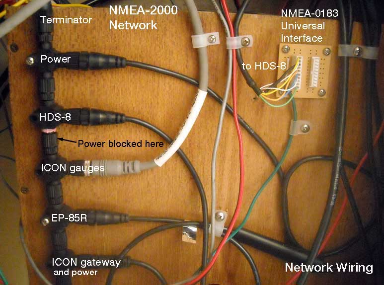
Here is how this network appears as installed. Note that the T-connectors are held to the bulkhead in only two places. Those fasteners are also not tightened completely. This leaves the assembly of multiple T-connectors free to align itself as it wants, based on the alignment of the actual connectors in each device. I think it is a mistake to mount every T-connector with a fastener and to tighten it firmly to the bulkhead. The pilot holes for the fasteners might not be perfectly aligned, and by firmly screwing-down each T-connector you could be creating a misalignment of that connector with its two mates. (Also note that I did not follow my own advice when I put this network together, that is, the power is not on the socket connectors but rather on the pin connectors toward the expansion portion of the network. I will have to correct this next time I get to it.)
There are several ways to block the power in the network backbone wiring in a T-Connector. A special power-block insert device can be used; or a regular T-connector can be modified.
The GARMIN company makes a special NMEA-2000 DeviceNET Micro connector device that can be inserted at any point in a network backbone or daisy chain of network T-connectors. It carries the signal and shield circuits through the device but interrupts the power circuit.
NMEA 2000® Power Isolator
https://buy.garmin.com/en-US/US/shop-by-accessories/connectors/nmea-2000-power-isolator/prod74432.html
This is a good method to employ to isolate the power on a network, but there is one problem: the physical arrangement of the actual connectors in the body of the plastic T molded part are not the same as other manufacturers. When this device is inserted in a daisy chain of T-connectors from other brands, for example Lowrance devices, the power block won't be oriented in the same plane as the rest of the connectors. This will make it impossible to mount the assembly of T-connectors to a bulkhead, as the Garmin connector won't be aligned correctly.
Another method to block the power is to modify a conventional network T-connector. This is the method used in my boat's network and shown in the illustration above. The contacts for the power circuit are removed from the actual connector. One method for accomplishing this is to work on the female (socket) connector. Using a drill bit that is smaller than the plastic hole in the connector body but larger than the tinned socket, the socket can be removed from the connector body. The wire attached to that contact can be cut off, the end covered with heat shrink, and the wire stuffed back into the connector body It is also possible to remove the male or pin connector. Of course, you have to be certain to remove the right contact. For guidance on contact layouts, see a separate article that shows the layout of the circuits in the connector:
NMEA-2000 Micro Connectors
http://continuouswave.com/forum/viewtopic.php?f=9&t=714
Depending on how you modify the T-connector and where it is inserted, it may or may not provide power to the attached device.