search | FAQ |
profile | register | author help
|
|
|
| Author | Topic: VHF Antenna: Shakespeare 5206C |
| jimh |
 posted 02-24-2007 02:02 PM ET (US)
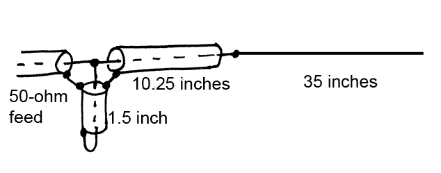
 Some time ago I damaged a Shakespeare 5206C antenna, an 8-foot inexpensive marine antennas with a fiberglass structure. This antenna and other like are it are often used on small recreational boats for VHF Marine Radio service. I discarded the fiberglass antenna, but I saved the internal components for analysis. The manufacturers of antennas of this sort often ascribe to them gain figures which are rather impressive. I was curious what exactly was inside the antenna and how it operated electrically. Here is a sketch of what the antenna contained:
Physically the antenna is made from three pieces of coaxial cable: the feedline, the stub, and the sleeve. These are all soldered together and covered with heat shrink tubing. The upper portion of the radiator is made from a piece of center conductor from RG-58 coaxial cable. The RG-58 feed line is a 50-ohm coaxial cable. It enters the base of the antenna and carries about four feet up the antenna. There the radiating portion of the antenna begins. The 10.5-inch coaxial sleeve in series with the radiator is made from RG-59, a 75-ohm coaxial cable. The 1.5-inch shorted stub is made from RG-58 coaxial cable. The 35-inch radiator is about one-half wavelength. The impedance of an end-feed half-wave radiator is very high, perhaps 1,000-ohms or more, so it cannot be fed directly from a 50-ohm feedline. The coaxial sleeve and shorted stub most likely operate as impedance matching devices to transform the antenna impedance closer to 50-ohms. Wavelength L = 984/f Thus for a VHF Marine Band of 156.8 MHz, one wavelength is 6.275-feet, or about 75.3-inches. |
| Chuck Tribolet |
posted 02-24-2007 02:27 PM ET (US)
So the REAL antenna starts five feet above the base, and the center of the REAL antenna is about six and a half feet above the base, right? It's also not Shake's finest. Whadidya do to damage it, Jim? Run under a bridge? ;-)
|
| wywhaler |
posted 02-24-2007 05:12 PM ET (US)
I believe the 10 1/4 in section of 75 ohm coax is known as a 75 ohm, quarter wave transformer. I used the same type of thing on my 80M horizontal full wave loop ant. SWR was flat in the part of the band I operated in the most. I prefer an antennas that's resonant but that full wave loop was the most quiet ant I ever put together. I usually make my own. I'm a Ham. Call is WR8O 73 Ron WR8O |
| jimh |
posted 02-24-2007 05:52 PM ET (US)
This fiberglass antenna demonstrated one of the characteristics of fiberglass antennas which is not their strongest point: very limited bend radius before fracture. I think I left the antenna up when I loaded the boat on the trailer. It made is almost all the way home until a low-hanging tree branch took its measure of the antenna. Re the transformer effect of a quarter-wave section of transmission line whose characteristic impedance is different than the main transmission line: this is a common technique used to make impedance transformations. The general rule for the case of a quarter wave long transmission line is that the characteristic impedance of the transformer section should be the geometric mean of the of the two impedances to be matched. If Za is the antenna impedance and 50-ohms is the desired impedance, the matching section, Zx, should have an impedance of Zx = (Za x 50)^0.5 In the case of this marine end-fed antenna, we know the impedance of the matching section, Zx, to be 75-ohm. Therefore we can manipulate the formula to get the antenna impedance: Zx^2 =Za x 50 Za = Zx^2/50 Za = 75^2/50 Za = 112.5 Unfortunately, the impedance of the nearly half-wave radiator as an end fed antenna is going to be much higher than 112.5 ohms. Also, the length of the 75-ohm section is too short to be a quarter-wave. A quarter-wavelength at 156.8-MHz would be L = (984/156.8) x 0.25 --or-- L = 18.826 inches So the 10.25-inch sleeve section seems too short to be a quarter wave. An alternative way to look at the function of the 10.25-inch sleeve is to consider it just part of the radiating element. Also we could include about 1.5-inches of the connections between the feed line and the stub. This would increase the overall length of the antenna to be close to 46.75 inches. This is an interesting dimension. In terms of wavelength, it is 46.75 /75.3 = 0.62 wavelength This is close to the popular "5/8-th" wavelength antenna. The feed point impedance of a 5/8-th wavelength monopole is much lower than a pure half-wave end fed. It is hard to deduce exactly how the antenna operates because the actual electrical characteristics will depend on how the antenna currents flow on the antenna. Also, the actual orientation of the shorted stub is parallel to the sleeve section. The coaxial cables all have their insulated outer conductors in place, but they are bent so run parallel and in a bundle. ANTENNA HEIGHT Chuck's comments about antenna height are cogent to my earlier article about VHF Marine Antennas and how the range of communication is affected by antenna height. This particular antenna was NOT the antenna that was on my boat prior to the installation of the elevated half-wave GAM ELECTRONICS antenna. The 8-foot antenna which was replaced by the elevated GAM ELECTRONICS antenna is also an 8-foot fiberglass antenna, but it was not a Shakespeare 5206C. THE 5206C is an inexpensive antenna, normally selling for less than about $50. The unidentified antenna which was on my boat before I installed the GAM ELECTRONICS antenna was quite different. It was much heavier and was to my eye one of the more expensive antennas in the Shakespeare line. I do agree with Chuck's characterization that this 5206C antenna is really more like a "4-foot" antenna hidden inside an 8-foot fiberglass tube. The other 8-foot antenna was more likely an antenna which had a true electrical length of 7-feet. |
| jimh |
posted 02-24-2007 06:07 PM ET (US)
Ron--I am also a licensed radio amateur. My callsign is K8SS, and I have been licensed (Amateur Extra Class) for over 40 years. I also held a FCC First Class Radiotelephone license until the Carter administration decided that it would be politically advantageous if the Federal Communication Commission stopped licensing radio engineers or requiring any sort of technical competence in broadcasting. Like all other licensees, I had to turn in my First-Class license and was given in return some politically correct substitute which no longer included a notion of any sort of graded level of competence. |
| wywhaler |
posted 02-24-2007 07:27 PM ET (US)
Jimh: Based on your post, I picked up the GAM SS-2 ant for our new 170 Montauk. We're going to try the Bimi-T-Top, so the VHF and GPS antennas will be as high as possible. On the other hand, I'm big on ICOM VHF and we're using the ICOM M422. Noticed that it finished #1 in a match-up on one of the websites( Saltwater something). Not sure what other brands were tested but I believe that ICOM is as tough as nails. I'm from the Detroit area and I enjoy your pictures. Certainly a contrast to what I'm looking at out my window here in Wyoming. 73 Ron WR8O |
| Chuck Tribolet |
posted 02-24-2007 07:39 PM ET (US)
BTW, Jim, I did something similar. Left the antenna up leaving Pt. Lobos. But I only made it a few hundred yards before I found the tree, and it was a Shake Galaxy, not a cheapie. I glassed the antenna back into the ferrule, and it worked fine, but I replaced it because my glass work was UGLY UGLY. It's still in the rafters of the garage.
|
| handn |
posted 02-25-2007 09:58 AM ET (US)
Having used both, I can attest to the fact that there is a huge difference in performance between the the Shakespeare cheapie and the Galaxie. I like Icom radios. The West Marine catalogue prints performance specs. Most radios have similar specs except the Icom 602 which has greater receiver sensitivity. However, there is a difference in transmit and receive clarity between radios with the same specs and an even bigger performance penalty if connections are loose or coroded or the cable is spliced. |
| jimh |
posted 02-25-2007 10:22 AM ET (US)
After giving some more thought to the analysis of the Shakespeare 5206C antenna, I think the coaxial sleeve just functions as a decoupler which tries to suppress antenna currents from flowing down the feed line. Such currents are a problem with an end-feed antenna like this one. I also have another Shakespeare antenna which was broken. When I get a chance I will disassemble it and see what is in that one. It is a more expensive model. Even though two antennas use a radiator whose length is similar, there is no guarantee they will both work as effectively, and particularly so with the case of these end-fed half-wave antennas. The impedance transformation is quite high, a ratio of over 10:1. Getting effective power transfer can be hard under those situations, and it is easy to have some loss in the matching network. One of the reasons why the GAM ELECTRONICS antenna seems to be more effective than the Shakespeare 5206C, even though they appear to both be half-wave antennas, is the design and construction of the GAM ELECTRONICS seems to have a much larger and robust matching section and the radiating element is significantly larger in diameter. Both of those factors would tend to contribute to less loss in the antenna and the matching section. That translates into more of the power from the radio actually being radiated by the antenna. In actual field strength measurment tests, the GAM ELECTRONICS antenna beat the Shalepeare 5206 by about 1.2-dB. However, one should not sell short the Shakespeare 5206C antenna--it outperformed a much more expensive Digital-brand 528-VW antenna by an astonishing 4-dB. The $30 Shakespeare will give you plenty of antenna for the money. (Test data from http://www.gamelectronicsinc.com/practical.html ) |
| jimh |
posted 02-25-2007 03:06 PM ET (US)
In the February 2007 issue POWERBOAT REPORTS tested several VHF marine antennas, including the Shakespeare 5206C. In their testing the 5206C came in dead last, and by quite a gap from the other antennas tested. The test technique was unusual and involved actual open water base-to-boat transmission. Whether or not their results are reproducible remains to be seen. Generally antenna testing is done on an antenna test range, all antennas are measured over an identical path, which is usually not more than several hundred feet in length, and measured in comparison to a base antenna or by actual measurement of received signal strength from a reference antenna transmitting at a constant power. In the POWERBOAT REPORT method the path was rather long, 6 to 23 miles, and atmospheric conditions may have varied somewhat from test to test. While their technique is fairly reasonable, it does not exclude outside effects. For example, a large ship might have passed through the antenna test range and affected the results. The POWERBOAT REPORT results correlated very well with antenna price and length, as they found the longer and more expensive antennas worked better than shorter and less expensive antennas. They did not test the GAM ELECTRONICS antenna. They also examined the internal construction of the test antennas and noted the relatively simple and inexpensive construction of the Shakespeare 5206C. |
| Bella con23 |
posted 04-13-2007 10:17 PM ET (US)
Jim (or anyone else): If I were to check the Shakespeare 5206C antenna for continuity, should I read a 50 ohm load across the coax cable? |
| jimh |
posted 04-14-2007 12:22 AM ET (US)
If taking a DC resistance measurement of an antenna, you will never see a reading of 50-ohms. The antenna's radiation resistance (to the flow of radio frequency energy) is 50-ohms, but the DC resistance is not. In the case of a Shakespeare 5206c the DC resistance will be close to zero ohms. |
| Bella con23 |
posted 04-14-2007 08:00 AM ET (US)
Thanks Jim. Guess I will be shopping for a new antenna this week. I'm reading an open on this antenna and my old (backup) as well. |
| Bella con23 |
posted 04-14-2007 11:01 PM ET (US)
Well this is confusing to say the least. I took a ride over to West Marine and purchased a Shakespeare Mariner 8700. Don't get me wrong, I needed to replace this original equipment antenna soon anyway. I unpackaged the antenna and quickly hit the lead-in cable with my Beckman volt/ohm meter. Infinite reading AGAIN. However, I did replace the antenna and fired up the new Icom 422 and keyed the transmit PTT. Low and behold it appears to be working fine as I had my son take a ride down the street with my scanner tuned to 156.425 (channel 68). I transmitted on low power and he said he heard me crystal clear. There has to be a static test for these antennas. My lead-in wire felt very loose so I thought that was the reason for the "open" circuit. |
| jimh |
posted 04-14-2007 11:57 PM ET (US)
It is perfectly normal for some antennas to measure a DC resistance of "open" or infinite. It all depends on how the antenna is constructed and how the transmitter power is coupled into the antenna. A simple way to assess the effectiveness of the radio system is to listen for remote weather stations. If you can hear a weather station from 30-miles away, things are probably working. |
Powered by: Ultimate Bulletin Board, Freeware Version 2000
Purchase our Licensed Version- which adds many more features!
© Infopop Corporation (formerly Madrona Park, Inc.), 1998 - 2000.