search | FAQ |
profile | register | author help
|
|
|
| Author | Topic: Trim Gauge Malfunction |
| atygert |
 posted 09-19-2003 10:16 PM ET (US)
 I just bought a 1991 Montauk that has a 70-HP Evinrude of the same vintage on it. While we were testing it out, the only item that didn't work was the trim gauge. The needle was at the bottom of the gauge all the time. I noticed there's a spring loaded lever on the back of the motor. This, I assume is the sensor for the trim gauge. Is there some place I can get a wiring diagram or a trouble shooting procedure for this system? Thanks--Allan |
| Bigshot |
posted 09-19-2003 10:38 PM ET (US)
If not the gauge, forgettaboutit! Too costly to bother unless a lose wire. The sensors go bad frequently and not cheap. With an outboard you go by feel of the pants when trimming it anyway. You can also hear when the engine is all the way down, etc. If an I/O then they help being you can't see the angle of the drive or hear the trim motor while running. |
| sturxph |
posted 09-16-2010 09:41 AM ET (US)
[This discussion was revived after being dormant for seven years.--jimh.] I have a [1985] Evinrude 90 [with] the same problem. The Gauge in the of the gauge is usally means the the sender wire is no sending. [Unclear to me--jimh] I [checked the resistance of the] trim sender, and [it] was fine. [I] checked the continuity of the TAN sender wire, and it was fine. I checked the BLACK-TAN isolated ground and it was not continuous with the BLACK. [The source of the malfunction] is either the gauge or the ground. I think. But, when I connect [the gauge] to the original wires and check the sender wire WHITE-TAN, [unclear] does not register any resistance or the gauge does not work. The gauge seems to work if I directly connect the sender to the gauge and the battery. There are two wires out of the sender: one TAN and one an isolated ground. I think the ground is bad. [Repair of the gauge] is not that important, but it would be nice to have the working trim gauge. [Tell me] how to check for a bad ground. |
| hauptjm |
posted 09-17-2010 10:04 AM ET (US)
[Changed topic to discuss necessity of using a trim gauge.] |
| jimh |
posted 09-18-2010 09:20 AM ET (US)
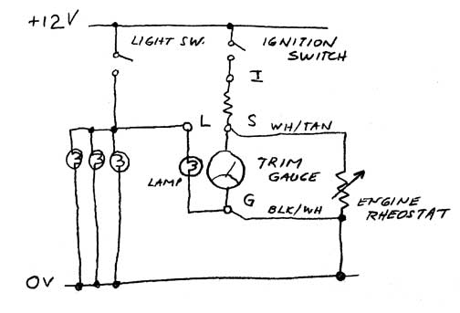
The electrical circuit of the TRIM gauge is very simple. View this simplified schematic diagram:
The connection to the battery ground is usually made near the trim sensor. |
| jimh |
posted 09-18-2010 10:58 AM ET (US)
If you need a detailed drawing of the electrical connections of the TRIM gauge circuit on your outboard motor, consult the service manual. OMC service manuals generally have very good electrical diagrams, printed in color, and showing the wiring in detail. They also include electrical troubleshooting and diagnostic procedures which are written on a very basic level which assumes the reader does not have a great deal of electrical expertise. If you have some electrical expertise, are familiar with simple DC control circuits, and have the appropriate test equipment, the simplified schematic diagram shown above should be very useful in investigating the problem. If otherwise, I recommend buying the service manual. Actually, I recommend buying the service manual if you intend to perform any service or repair on your motor. To attempt repair or service without the service manual is to invite problems. |
Powered by: Ultimate Bulletin Board, Freeware Version 2000
Purchase our Licensed Version- which adds many more features!
© Infopop Corporation (formerly Madrona Park, Inc.), 1998 - 2000.