continuousWave --> Whaler --> Reference --> Chart Plotter Interface in Digital Selective Calling
Chart Plotter Interface in Digital Selective Calling
by James W. Hebert
This article examines the response of a chart plotter to data sent to it via a wired digital interface from a DSC radio. The DSC radio sending the data and the chart plotter are both made by the same manufacturer, Lowrance. They are a LINK-8 radio and HDS-8 chart plotter.
This article is the fourth article in a series of four article I have written in which the behavior of DSC radios is tested and examined. The index below provides access to all four articles:
Digital Selective Calling
Digital Selective Calling or DSC is a new technology in marine radios. It permits one radio to make a call to another specific radio, and pass information to the radio receiving the call in a digital manner. The two radios communicate back and forth by exchanging digital radio messages. This link happens over the radio airwaves, and by complicated modulation of the carrier signal. It is extremely difficult to observe this process in action, and it will not be observed here. However, there is a very strict specification or recommended standard that governs this exchange of data between the radios, as well as how the radios will present an interface to their operators: ITU-Rec. M.493-13, an open and freely available recommendation from the International Telecommunications Union. The communication between the radios can thus be observed through their displays and controls.
There is also a provision in this standard that the radios can communicate via wired data links to other electronic equipment on board. The most common wired link is to connect a GNSS receiver and a DSC radio so that the radio is automatically provided with the present position of the vessel from the GNSS receiver. A less common but also important link is to connect the radio with a chart plotter or other navigation display. The radio can then send data to the chart plotter that it has received from other DSC radios.
The manner of exchanging data between a DSC radio and other electronic devices is to be in accordance with another specification, IEC-61162, published by the International Electrotechncial Commission. (This specification has several parts. The IEC-61162-1 portion is believed to be extremely similar to the NMEA-0183 specification often mentioned in regard to data links between marine electronic devices. Hereafter this will be referred to as NMEA-0183. The IEC-61162-3 portion is believed to be similar to NMEA-2000. Hereafter this will be referred to as NMEA-2000) Unfortunately this specification is not available for free, and its contents are protected by copyright and may not be reproduced without permission. I am not an expert on the complete recommendations of IEC-61162, NMEA-0183, and NMEA-2000, but their application in a DSC radio connection to other electronics seems to deal mostly with how to format datagrams to be sent from or to a DSC radio. Data from a DSC radio is sent to other electronic devices via NMEA-0183 primarily in one particular datagram, called DSC, typically sent as $CDDSC, and often supplemented by a data expansion message, called DSE and typically sent as $CDDSE. In the case of data being sent from a DSC radio to another device, neither NMEA-0183 or NMEA-2000 does not, as far as I am aware, specify precisely what these other devices will do when they receive the datagrams from a DSC radio. The purpose of this article is to investigate that situation.
The Test
To conduct an investigation, a test or experiment was devised. A radio under test sends a DSC call to another DSC radio nearby requesting its position. The other radio replies with the requested information. The radio under test is connected to a chart plotter under test, and the radio sends data to the chart plotter that is a result of the DSC call it has just received. The response of the chart plotter under test is then observed and analyzed. A further aspect of the test is to use different methods of interconnection for the wired data link. Two methods are used: one in accordance with NMEA-0183, and a second method in accordance with NMEA-2000. The test also examines any variation in the outcome that seems to vary with the network connection.
The Test Equipment
The equipment used was somewhat limited in scope. The DSC radios were only Class-D devices, which limits the range of digital selective calling features they can provide. The chart plotter was a recent model, made by the same manufacturer as the radio to which it was connected. This should provide excellent compatibility in terms of the encoding of the data the radio will send, and the decoding of the data at the chart plotter when received. The DSC messages exchanged were limited to a single function, the requesting of a position by one vessel to another.
In addition to the radios and a chart plotter, a data terminal was also used. This allowed the actual data being sent on the NMEA-0183 interface to be captured and examined. Unfortunately, no equipment was available to capture any data from the NMEA-2000 network interface, so that data has not been examined.
Radio Under Test
A Lowrance LINK-8 was used as the radio under test. This radio provides both the NMEA-0183 and NMEA-2000 interfaces necessary. The radio is a recently designed and engineered product and is said to conform to the M.493-13 specifications for DSC Class-D.
The Other Radio
A Standard-Horizon GX1500S was used as the other DSC radio. Although this radio was actually also interfaced with some of the other equipment—it got its automatic position update from the chart plotter's GNSS receiver—it could have been remotely located. Its only role in the test was to respond to a DSC call. It is rated as a Class-D radio, but to a slightly earlier version of M.493 that was in effect in c.2005.
Chart Plotter Under Test
A Lowrance HDS-8 was used as the chart plotter under test. Data from the GNSS receiver in the HDS-8 was fed to the radio under test via NMEA-2000 (and also fed via NMEA-0183 to the other radio to give it a position). Data from the radio under test was fed to the HDS in two ways: first, data was fed via a NMEA-0183 connection, and then later by an NMEA-2000 connection.
The Test Procedure
The test was conducted according to the following procedure:
- the two radios were set up at a convenient distance so they could easily communicate with each other via radio while connected to dummy loads to minimize any radio emissions;
- the radio under test was connected to a GNSS receiver via a NMEA-2000 network;
- the radio under test was connected with a chart plotter via an NMEA-0183 connection;
- the other radio is configured to get its position from a GNSS receiver, and to automatically reply to position request calls.
- the radio under test sends a DSC call to the other radio requesting a reply with its position information;
- the other radio receives the DSC call and complies automatically with the request, transmitting back an acknowledgement DSC call with the position data without any user intervention.
- the radio under test gets the reply from the other radio, and performs several actions, described below in the test results;
- the radio under test outputs data on its wired interfaces;
- the chart plotter receives the wired data on its NMEA-0183 interface;
- the chart plotter produces a combination of actions, which are described below in the test results;
- the wired connection between the radio under test and the chart plotter is changed to an NMEA-2000 connection; and,
- jump back to step 5 and repeat the test procedure through step 11.
The Test Results
DSC Radio Response to Call
There was no difference in the behavior of either radio involved in the test when the wired connection of the radio under test to the chart plotter was changed. Upon receiving a DSC reply from the other radio, the radio under test responded with with an aural alarm to alert the operator a reply had been received to its digital selective calling request for a position. The alarm was at a quiet loudness level and could be silenced by a soft-key button in the user interface. The display showed the MMSI of the other vessel (or the name associated with that MMSI in the radio under test's local directory), the nature of the call (position reply), the position of the other vessel, and the time of the call. The radio logged the call in its non-distress DSC call log. (An image below shows the logged call; unfortunately, I did not record an image of the display when the call was first received.) These results were completely consistent with the nature of the call received, and seem to conform with ITU-Rec. M.43-13, as they should.
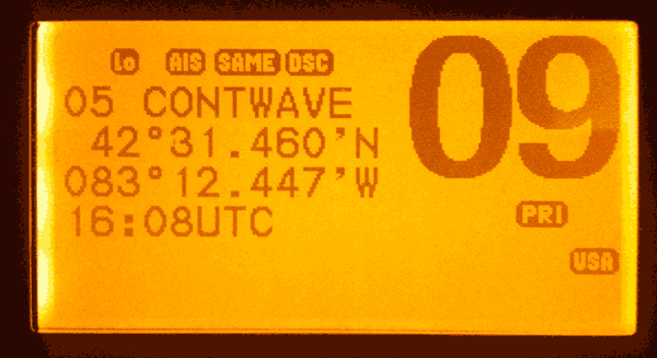
The LINK-8 call log entry number "05" shows the time and position of the position reply call.
The vessel name "CONTWAVE" is taken from the radio's own directory listing in which a vessel
MMSI is associated with a nemonic. Note the time is correctly shown as 1608-UTC, or a few
minutes past noon local time.
Chart Plotter Response to Call
The response of the chart plotter to the test calls was significantly different depending on the method of connection between the chart plotter and the DSC radio sending the data. Also, in both methods of connection, there were discrepancies noted in the information displayed. These are explained in more detail below.
NMEA-0183 Connection
With the chart plotter receiving data from the radio via a NMEA-0183 wired link, it was possible to capture the actual datagram sent by the radio. By having the actual datagram, it was possible to see precisely what information was being sent to the chart plotter. Based on this knowledge, the response of the chart plotter seems rather unexpected and inappropriate.
Datalink Datagram Captured
The data being sent to the chart plotter was captured by the data terminal. There were two datagrams sent to the chart plotter from the radio:
$CDDSC,20,3380400790,08,21,26,1423108312,9908,,,B,E*72
$CDDSE,1,1,A,3380400790,00,46094473*19
Based on my earlier investigation into these datagrams, the first datagram (beginning $CDDSC) is of call type or format specifier "20" or "Individual", and it is not a distress alert message. This is followed by the MMSI of the sender. Next is the category: "08" or "Safety." This is followed by the First Telecommand: "21" or "Ship Position". Next is the Second Telecommand: "26" or "No Information". The ship position follows, but only to whole minutes: 42-degrees 31-minutes by 083-degrees 12-minutes North and West. Next the time in UTC: "9908". (Whoa—that does not look right. The time was just after local noon. Time is to be sent in UTC in a 24-hour format, so there is never any time which would be sent with the hours field as "99". This is a mistake in the radio in generating this datagram.) Two blank fields follow. Then the End of Sequence indicator with Acknowledged Back specifier, "B"; a notice that an expansion message will follow, "E"; and the checksum.
The second datagram (beginning $CDDSE) is an expansion message that gives the position in decimal minutes for latitude and longitude.
Other than the unusual time stamp, this message looks rather plain. How the HDS-8 responded to it was unusual.
Response of HDS-8 Chart Plotter
The HDS-8 chart plotter responded to getting the above datagram on its NMEA-0183 serial port as follows:
- a visual alarm popped up on the chart display, announcing "Alarm - Vessel message. From: [MMSI] Undesignated distress";
- a waypoint was created at the position contained in the message. In the details of the waypoint the description said, "Undesignated distress."

Upon receiving notice of a individual call of category "safety", the HDS put this visual alarm
alert on screen. The use of the description "Undesignated distress" seems completely inappropriate.
The presentation of the non-distress call is identical to the presentation given to an actual distress call.
The same screen alarm pops up. If the distress message was sent with a nature of distress, that
will be shown for the distress message alert, but other than that distinction, the alarms are identical.

The HDS created a waypoint at the position sent by the DSC call. The details of the waypoint
reveal a description as "Undesignated Distress." Again, the call received was not a distress
alert call, but rather a reply to a position request, sent with the category "safety."
This response is rather unusual. The actual DSC message was clearly not a distress alert message, but rather an individual ship message. The category was "Safety", and there was a clear designation: a position report. The response of the HDS-8 is not very appropriate to the actual message sent via radio, nor to the actual datagram sent to the chart plotter on the NMEA-0183 wired data link.
NMEA-2000 Connection
With the chart plotter receiving data from the radio via a NMEA-2000 wired link, it was not possible to capture the actual datagram sent by the radio. The response of the chart plotter was different than when a different connection method was used.
Datalink Datagram Not Captured
Unfortunately, I don't have any means to capture the actual datagrams being sent by the radio on the NMEA-2000 network, and this detail is not available. This creates some ambiguity regarding the cause of the variation in response of the chart plotter to the data. We cannot tell if the chart plotter response changed due to some difference in the data it received, or if the same data was received as before, but the chart plotter responded differently
The unusual time stamp noted in the NMEA_0183 datagram appears to also have occurred in the NMEA-2000 data, because the time stamp of the waypoint creation is set at 12:00 a.m., which was incorrect. I suspect that the LINK-8 sent badly formed data for the time in the NMEA-2000 datagram, just as it did in the NMEA-0183 datagram
Response of HDS-8 Chart Plotter
The HDS-8 chart plotter responded to the datagram on the NMEA-2000 network from the radio as follows:
- no alarm pop-up occurred on screen;
- a waypoint was created at the position contained in the message. In the details of the waypoint the description said, "Grounding Buddy."
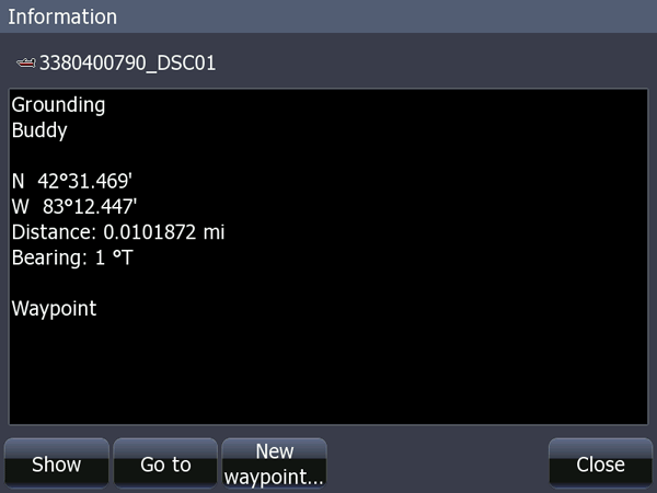
In responding to data on the NMEA-2000 interface, the chart plotter created this waypoint.
Note the description is "Grounding Buddy.
This seems like an unfortunate mixing of categories,
both official and unofficial.
As mentioned earlier, the category of the DSC reply was "Safety", and there was a clear designation: a position report. There was no data sent that reflected a grounding—it appears that would only be appropriate in a distress alert message. The nature of distress as "grounding" is set by symbol code 103. In the field for First Telecommand, the symbol 103 is used for "polling." Apparently what was intended was to convey a notion of having polled a "buddy" boat has somehow been incorrectly interpreted as a grounding. The most curious thing is there is no provision made in M.493, IEC-61162, NMEA-0183, or NMEA-2000 for a designation of "buddy." This must be some invention of Lowrance, and not an international standard for digital selective calling.
Analysis of Test Results
The test brings together many elements of a complicated communication system. We have two radios, a chart plotter, and two methods of connecting the chart plotter to the radio under test. The test results are a mixture of success and failure. The communication between the radios and the data they displayed to the operators, which are all covered by ITU-Rec. M.493, worked well and showed consistency. The communication between the radio under test and the chart plotter under test indicated there was communication, but the interpretation of the actual information exchanged via digital selective calling was not always correct.
The inconsistency in the interpretation of the data being sent to the chart plotter under test from the radio under test is troubling. Both devices are made by the same manufacturer. One would anticipate that given a complicated communication system defined by many overlapping standards, there could be some variations in how those standards are interpreted. But, among the products of a single manufacturer, one would hope for consistent application of standards. This was not found to be the case in this test.
Perhaps the most important data, the position of the other vessel, was exchanged and presented on the chart plotter correctly, so we can be pleased with that outcome. But details about the call were incorrectly presented. On the NMEA-0183 interface the call was presented in a manner that might be interpreted as a distress alert of an undesignated nature. On the NMEA-2000 interface the call was presented as coming from a vessel aground. In the case of the NMEA-0183 interface, the error appears to be due to problems in the chart plotter and its ability to interpret correctly the actual data contained in the DSC datagram. In the test of the NMEA-2000 connection, we could not observe the actual datagram, and identifying the source of the error is more difficult. The NMEA-2000 datagram could be slightly different in its content, or the datagram could contain the same data as its NMEA-0183 counterpart and the chart plotter just interpreted it differently. More test equipment will be needed to capture the NMEA-2000 datagram, and more information about the format of NMEA-2000 datagrams related to digital selective calling will also be needed, if the cause of this discrepancy is to be isolated.
Another problem observed was the information about the time of the call. The time of the DSC call was apparently mangled in both the NMEA-0183 and NMEA-2000 datagrams, and this appears to be due to a problem in the radio under test. This is likely to be due to some mistake in creating the DSC datagram in the radio's data processor.
As a complex communication system, the radio-to-radio links seem to be the most well defined; they are given in an open standard, although the description of them can be a bit confusing. The radio-to-chart-plotter links seem more prone to confusion. Due to not having made an intense study of the various standards and recommendations that might apply to this part of the system, it is hard to judge what errors have been made. The NMEA standards seems to be mostly concerned with the format of the datagrams that will be sent and electrical and electronic details of the communication process. Precisely what a chart plotter ought to do when it gets one of these datagrams seems much less well defined, as far as I can tell. At the least, one would hope that a chart plotter receiving a datagram from a DSC radio made by the same company would correctly decode the datagram and present the actual information it contained. This outcome did not occur in this test.
This is a verified HTML 4.0 document served to you from continuousWave
Author: James W. Hebert
This article first appeared May 13, 2014.

