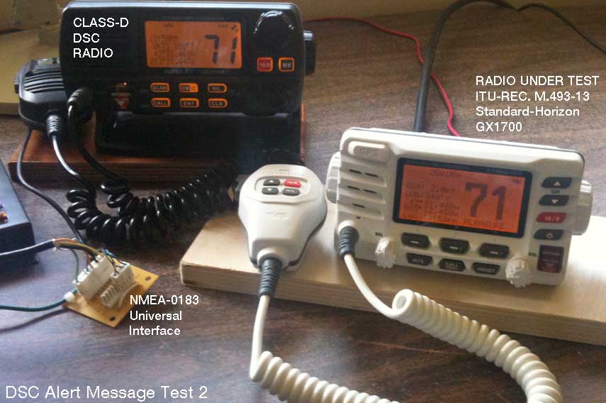
The Standard-Horizon GX1700 radio on the test bench. The chart plotter (not shown) is connected to the bench's Class-D radio receiver
via NMEA-0183 using my Universal interface method.
The second in a series of articles testing digital selective calling radios for their distress alert messages
This article is the second article in a series of four article I have written in which the behavior of DSC radios is tested and examined. The index below provides access to all four articles:
This is the second article in which I test a VHF Marine Band radio with digital selective calling (DSC) features for sending a distress alert message. Please see the initial article for some background on the test methods and prior test results. The results reported in this article are for a current-model VHF Marine Band radio that conforms with Federal regulation 47 CFR 80.225 for a Class-D DSC radio. Those regulations cite ITU-Rec. M.493-13 for the requirements of the Class D DSC radio features. ITU-Rec. M.493-13 is the most recent recommendation from the ITU, and it represents considerable evolution in the requirements from their initial drafting. In the USA at the present time, all new fixed-mount VHF Marine Band radios offered for sale must conform to these specifications.
The radio under test in this article is a Standard-Horizon GX1700 model, a current model, and accepted by the FCC as compliant with ITU-Rec. M.493-13. The radio had software revision 2.00. The serial number was in the sequence 3D2528nn.
The test involved four devices:
The GPS receiver, chart plotter, and DSC Class-D radio used for a test receiver were connected together via NMA-0183. For details of the NMEA connections, see the initial article. In this instance, the radio under test has its own GPS receiver, and gets its position data from its internal GPS receiver. As a result, there were no interconnections of the test radio to the GPS receiver or chart plotter. The two GPS receivers deduced slightly different positions, as is to be expected. Neither of the GPS receivers during the test was getting an enhanced precision fix from satellite based augmentation systems (SBAS) like the wide area augmentation system (WAAS) available from the FAA, and their deduced positions could thus be different by perhaps a distance of 100-feet or more.
I connected the radio under test to a 50-Ohm dummy load with a short length of RG-213/U transmission line. I connected a quarter-wave whip antenna to the Class-D radio used as a test receiver, and placed the antenna a few feet from the dummy load.
The Standard-Horizon GX1700 radio on the test bench. The chart plotter (not shown) is connected to the bench's Class-D radio receiver
via NMEA-0183 using my Universal interface method.
The test is primarily interested in determining:
My test results were not particularly surprising, that is, the outcome obtained was mostly as I expected it would be. The Standard-Horizon GX1700 was simple to configure for automatic position data, the distress alert was easy to compose and send, and the distress alert message allowed other modern Class-D DSC radios to know the position of the vessel in distress to a very high resolution. This outcome is anticipated for radios that comply with ITU-Rec. M.493-13.
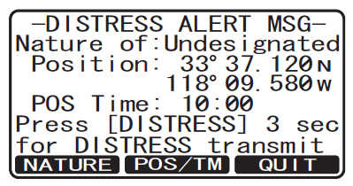
I lifted the red cover marked DISTRESS on the test radio, and pushed the button under it, also marked DISTRESS. The radio emitted a moderately loud beep, and the display changed to a new screen, with appearance like this:
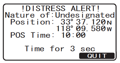
If the DISTRESS button is pushed once, a screen
similar to the above is presented.
(Please note: for this illustration and others I have borrowed screen captures from the radio's literature to show the appearance of the screen display. The time and position data are not those used in the actual test.)
QUIT is a legend for one of the soft-key control buttons below the screen. If you push the QUIT soft-key button, the radio makes a quiet double-beep and returns to normal operation. If you do nothing, this screen remains, awaiting some further action. The operator must make an inference that he should push and hold the DISTRESS button to actually initiate a distress alert message to be sent. Whether or not this will be clear to someone not familiar with this particular radio is hard to judge with certainty, but I am inclined to think the instructions on screen are not sufficient to be certain to cause an untrained person to press and hold the DISTRESS button.
On the other hand, operation of this particular radio does require that some buttons be pushed and held to cause certain optional operations to occur, so perhaps an operator familiar with this radio's user interface will have some intuition that the DISTRESS button needs to be pushed and held to cause a distress alert message transmission to occur. This requirement of the DISTRESS button operation is mention in the instruction manual, but no special emphasis is given to it. I could only find it mentioned once.
If the DISTRESS button is pushed again and held, a louder and more urgent sounding tone occurs at one second intervals, and with each beep the screen blinks and refreshes with the time counting down: Time for 3-seconds, Time for 2-seconds, Time for 1-seconds, down to zero. If the DISTRESS button is released before the countdown ends, the screen reverts to the above display. You can try pushing the DISTRESS button again or hit QUIT .
If the DISTRESS button is held for more than three seconds, the radio goes silent, the screen announces the radio is transmitting, and the distress alert message is sent via digital signal calling methods.
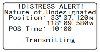
The radio display announces it is transmitting the distress alert message.
After the distress alert message was transmitted, the screen changes again, as shown below:
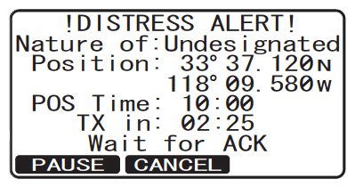
The radio display seen after sending a distress alert.
This new screen conveys important information. First, it shows the countdown timer that will determine the next automatic distress alert message re-transmission. (Shown above as two-minutes, 25-seconds.) Next, it describes the current state of the DSC radio, awaiting an ACK (acknowledgment) reply from another station. Then it offers two more options, PAUSE and CANCEL .
From here if you select the PAUSE option the automatic re-transmission countdown timer stops, and invokes a new screen that offers options to resume the countdown or cancel. Or, if you selected the option to CANCEL , another entirely new screen appears, offering to send a new DSC message that cancels the distress alert message just sent.
In my testing, I selected the option to cancel the distress alert message. The radio went into transmitting mode, sent the cancellation message, and then gave an on-screen prompt instructing that the operator should make a voice transmission on Channel 16 announcing the cancellation. The screen gave a suggested script for the message content that read:
All ships (3 times) This is vessel <ship name>. Distress message from MMSI number [here the radio's MMSI was inserted in the text] is canceled. (Repeat above 3 times)
A few seconds after the test radio sent the distress call, the test receiver began to emit a very loud warbled tone resembling a French police siren. The Class-D bench test receiver has a large alpha-numeric display, and it announced a distress call had been received.
The chart plotter display announced an alarm: "Undesignated distress call received from [MMSI number]." It marked the position with a waypoint icon.
The Class-D radio that received the distress transmission via DSC could be stopped from beeping by hitting its CLR button. I then found that I could scroll through the distress message using the main large rotary knob of the radio. The distress message payload was shown, consisting of:
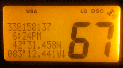
The distress alert call details as seen on another Class-D DSC
radio that has received the call. The position is shown with a
resolution of 0.001-minute.
The chart plotter was also showing the position of the vessel in distress; it had automatically created a new WAYPOINT at that position. The waypoint was automatically named with the MMSI of the sending vessel and the suffix DSCnn, where nn was the next available number in the DSC call log.

The chart plotter has plotted the position of the vessel sending the distress alert.
Since the chart plotter and the radio under test were getting their position data from independent GPS receivers, I expected the location of the vessel sending the distress message would be a slightly different location from the chart plotter itself. The distress vessel was located to the South and East of the chart plotter's position, about 72-feet away. This is huge improvement compared to the earlier test, in which the vessel in distress was plotted as being 0.65-miles away, even thought the same GPS position was used for both vessels.
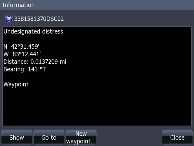
The distress alert call details as seen on a chart plotter that is connected to a Class-D DSC
radio that has received the call. The position is shown with a resolution of 0.001-minute.
The test revealed almost no problems in the transmission of a DSC distress message using this newer Class-D DSC radio conforming to ITU-Rec. M.493-13, whereas the prior testing of an older DSC radio showed three areas of difficulty. Reviewing the test criteria, I found
There was no problem of interfacing the radio under test to a GPS receiver because this was done internally in the radio itself, using a built-in GPS receiver. While this is not a requirement of the ITU-Rec. M.493-13, that recommendation does allow for integration into a DSC radio of an "internal electronic position fixing device" (See Secion 12.7).
The GX1700 manufacturer, Standard-Horizon, has incorporated an internal GPS receiver as a feature of their DSC radio. It is a darn good feature. Not only does it avoid the difficulties of interconnecting the radio to an external GPS receiver, but it makes the radio an independent device. If the radio has power and an antenna, and it can see the sky to get signals from the satellites, it will be able to send a distress message with a high-resolution position no matter what else happens to other electronics on the boat.
The on-screen guidance regarding the need to push and hold the DISTRESS button to send a distress alert message was not always explicit. There was information in the test radio's documentation to explain how to initiate a distress message, and it mentions that the DISTRESS button must be held. Instructions to push and hold should be presented on-screen.
The radio takes advantage of the latest ITU recommendations to send a high-resolution position fix for the location of the distress. This outcome is what was expected. It would be crazy in year 2014 to not send all the data available for the position fix. This radio does what should be done, according to common sense and the ITU recommendations. This is a distinct improvement compared to an older radio previously tested.
My test of this Class-D per ITU-Rec. M.493-13 radio sending a distress message produced mostly very positive results. I was extremely pleased by the simplicity of interfacing the radio and a GPS receiver: it was already done for me in the radio. (I examine interfacing the radio to an external GPS below.)
I was anticipating the radio would provide clear instructions on its display to push and hold the DISTRESS button for more than three seconds in order to initiate the transmission of the distress alert. The screen presented did not have this information. The screen display is capable of presenting any sort of text, so it should have given clearer instructions. Perhaps instead of saying "Time for 3-Seconds," the screen could say "Hold DISTRESS button for 3-Seconds." (The radio does provide an on-screen notification to hold the distress button for three seconds when the distress alert message is composed by first using the CALL button to select another method. See below for more details on the second method.)
When a distress message was sent, I was pleased in the outcome. My distress message was transmitted with an expansion message that gave the a position with high resolution. This allowed other Class-D DSC radios to know the position with very high resolution. This is a significant advantage of a newer DSC Class-D radio compared to older DSC radios. To better understand the various regulations that combine to require the higher resolution of position to be sent, see the Addendum of the first article in this series.
There are two methods or paths that can be taken to compose a distress alert message for transmission. As described above, the operator can simply lift the red cover and press the DISTRESS button for three seconds, causing a distress alert message to be sent with the Nature of Distress set to Undesignated. The radio's literature describes this method under the heading "Basic Operation." A second method is also available, described under the heading "Transmitting a DSC Distress Alert with Nature of Distress."
To transmit a DSC distress alert message that includes the Nature of Distress set to something other than Undesignated, the operator must first push the CALL button, which branches to the DSC MENU. On the DSC MENU the following options appear:
If the option Distress Alert MSG is selected, the DISTRESS ALERT MSG screen appears, which looks like this:
The DISTRESS ALERT MSG screen allows setting the Nature of Distress for the message that will be transmitted.
From the DISTRESS ALERT MSG screen, the operator can push the NATURE soft-key button, which will lead to a new screen that gives a list of categories for the Nature of Distress according to:
The operator can scroll the list and select the desired option by pushing a SELECT soft-key button. When this is done, the display returns to the DISTRESS ALERT MSG screen, and the radio waits for the operator to push the DISTRESS button to actually transmit the message. Note that the DISTRESS ALERT MSG screen has explicit instructions to the operator to push the DISTRESS button for three seconds to transmit the message.
The GX1700 also provides several additional features that are not required in any digital selective calling recommendation, but are very useful features associated with having a DSC radio.
DSC radios that comply with ITU-Rec. M493.13 "should be provided with facilities for exchange of data from shipborne navigational equipment or systems, or other shipborne equipment as necessary in accordance with IEC-61162 for purposes including automatic position updating." (The standard IEC-61162 is an international standard that is very similar to or the equivalent of the NMEA-0183 protocol.) The GX1700 provides for connnecting an external GPS receiver using the radio's NMEA-0183 interface, the test radio has a modern NMEA-0183 port that uses differential signals. The radio's literature describes the signal names and wire color code in a clear manner, although the recommended signal names of TALKER A/B and LISTENER A/B are not used. The wire color codes are clearly indicated. Standard-Horizon, the maker of the radio under test, has been very consistent in their use of the wire color codes they have chosen. Consistent use of a particular wire color code is not always found in equipment from other NMEA device manufacturers.
Configuring the radio to use an external GPS receiver as the source of position data may be useful with installations where the radio's internal GPS receiver may not be able to reliably receive satellite signals, or when it is desirable to use an external GPS receiver for other reasons. The literature for the test radio indicates an external GPS should send any of the following sentences: GSA, GSV, GLL, GGA, and RMC, with RMC being recommended for position information. These sentences were tested individually, and all were found to be accepted by the radio. Note that GSA and GSV do not provide position data; they provide information about the satellites in view and the satellites used in the position solution, but no actual position information. If the GSV data is availble, the radio has an option to display the satellite data on screen using an azumith-elevation polar chart. It can also display satellite data for its own internal GPS receiver with this display.
The test radio can also be configured to send output from its internal GPS to the NMEA-1083 port. In that way the position data from the radio can be sent to other devices that may want to use it.
The test radio will output NMEA sentences DSC and DSE containing data after it has received from certain DSC calls. Many older DSC radios will not have this feature, as they do not have any NMEA TALKER output. Again, the ITU-Rec. M.493-13 stipulates that such an interface should be provided for "exchange of data," which seems to suggest that the exchange can be in either direction. The GX1700 provides this feature.
The NMEA TALKER signals from the radio were connected to a modern chart plotter (an HDS-8) via NMEA-0183 interface and found to work properly. If the test radio initiates a DSC call for position request, when the radio receives a reply, it outputs the position data received from the other vessel a DSC sentence (and DSE sentence if available) to the chart plotter. The chart plotter responds by plotting the position of the other vessel, usually including marking the position with a waypoint. In a similar manner, the test radio will output the position of a vessel sending a distress alert message. With the position marked by a waypoint on the chart plotter, the chart plotter's navigation functions can be used to compute a distance and bearing to the waypoint.
While not part of the digital selective calling functions, the test radio incorporates several navigation functions. The navigation functions are primarily related to computing the distance and bearing to stored waypoints. The stored waypoints can be manually entered, or can be waypoints saved from positions received by the DSC radio from DSC calls or messages. The display of the radio can function as a very small track plot display, showing the relative position of waypoint navigation targets to the boat position. Typically these functions would be provided by and performed on an external chart plotter, but, in the absence of such a chart plotter, the radio has the necessary navigation computer and track plot display to provide these functions.
I will reply via email to any to inquires or comments emailed to me.
DISCLAIMER: This information is believed to be accurate but there is no guarantee. We do our best!
This is a verified HTML 4.0 document served to you from continuousWave
Author: James W. Hebert
This article first appeared March 28, 2014.
