Overboard indicator fitting is callout 32 above.
This article is a collection of several previously published articles on the general topic of re-powering my Boston Whaler boat with a new Evinrude E-TEC engine. A separate article deals with some advanced topics of E-TEC rigging. There is also a more recent collection of information about Evinrude I-Command, ICON Pro, and ICON Touch gauges in the forum.
In August of 2009 I re-powered my boat with a 2010 E-TEC 225-HP engine. The old engine was a 1992 Evinrude V6. My old engine rigging was originally all c.1992 components, but in 2006 I updated the rigging to include a System Check gauge by installing the System Check upgrade kit from Evinrude. Because of this my rigging was more prepared for the E-TEC than it otherwise would have been. A System Check gauge is necessary for rigging an E-TEC (unless I-Command is used). The upgrade kit also gave me the newer style oil reservoir float assembly and float switch. The upgrade kit also provided the new wiring harness to carry the System Check signals from the engine to the helm.
To switch from this hybrid rigging to the E-TEC, my dealer, Lockeman's Boat and Hardware in Detroit, exchanged the wiring harness adaptor from the rigging kit for a different harness adaptor that would work with the E-TEC. The wiring harness I had from the System Check upgrade kit adapted my pre-1996 engine to the System Check gauge. The E-TEC engine has the post-1996 rigging, called the MWS wiring (for modular wiring system, perhaps). I needed a different adaptor, one that would fit my old boat rigging to the new engine.
My old wiring adaptor was installed between the boat rigging and the engine. The existing rigging on my boat from the helm to the engine terminated in a large red multi-pin connector used on OMC engines for many years. The old adaptor mated to this big red connector and extended the harness about 8-feet to terminate in another big red connector at the engine. The old adaptor also provided the right connectors to mate up with the trim and tilt controls and the trim gauge leads, too, which are in a five-pin rubber Amphenol half-round connector. And the adaptor also provided a place to plug in the new System Check harness, and eight-pin Deutsch connector.
The new adaptor for use with the E-TEC has the Modular Wiring System (MWS) connectors on the engine end, and the old red engine connector and five-pin Amphenol trim-tilt harness at the other end. By changing to this adaptor, I could plug the new E-TEC into my existing top-mounting remote controls with the ignition switch, safety lanyard switch, neutral safety switch, and fuel-enrichment switch, and also plug into my existing trim and tilt switches and gauges.
The E-TEC harness adaptor looks like this:
HELM END   ------------------------ ENGINE END

Red main harness connector -------- MWS main connector

Five pin TRIM connector ----------- MWS trim connector

MWS System Check connector -------- MWS System Check connector
There was one minor modification needed. Because my older trim gauge installation used an isolated ground conductors on the TRIM gauge, it needed the BLACK with WHITE STRIPE conductor in the trim harness to be carried through to battery negative. For some reason, this circuit is omitted in the adaptor harness. It probably is no longer used with newer gauge wiring. Since it was easier to work with the adaptor connector than to tear apart my helm station to add the ground, I modified the adaptor harness to add the BLACK with WHITE STRIPE circuit to the adaptor side of the harness. I added a new socket to the connector (at "C") and wired the line to the battery negative at the battery negative terminal distribution bus nearby. That fixed the problem with the TRIM gauge isolated ground circuit. This may affect others who are using older gauges and the isolated ground return for the TRIM gauge.
For more about the TRIM gauge isolated ground circuit, see a separate article which gives more details.
The adaptor wiring harness is
CABLE ADAPTOR, 10 FT, PN 0176383, about $90.
If you need the whole conversion kit, it is called
ENGINE CABLE ADAPTOR KIT, 95-BOAT to 96-ENGINE, PN 0176345,
about $287, and gives you the new oil tank and many other components. You can see these on the SHOP2.EVINRUDE.COM website. Use the part category
OB ACCESSORIES ---> 1996 ----> ELECTRICAL 1996
Until July of 2010 I used my existing Evinrude mechanical remote throttle and shift controls along with my existing conventional gauges, ignition key switch, safety lanyard, trim and tilt controls, and so on, with the E-TEC engine. This system worked beautifully. In July of 2010 I changed everything to the new Evinrude ICON electronic remote controls and also changed all the gauges to the new Evinrude ICON gauges. These changes are not described in this article. Instead of adding that material here, I have written three additional articles:
Please see those three separate article for more information on electronic controls, the digital ICON gauge system, and how to convert an E-TEC to ICON controls. You will find a wealth of first-hand experience given in them.
After re-powering with an E-TEC, the evolution of the rigging was to add the I-Command or NMEA-2000 interface cable to the E-TEC engine. I added this after all the other rigging was done. This turned out to be a bit more complicated than I originally thought. The I-Command Engine harness assembly from BRP has the connectors already installed. The engine-side connector is larger than the network side connector, so you have to feed the harness through the rigging grommet from the engine side. As it happened, my rigging had already filled up most of the room in the rubber grommet, and I could not get the small DeviceNet circular through the grommet. To make more room, I had to remove an exiting cable from the grommet. The main battery cable proved to be the easiest to quickly disconnect.
Once I got the harness through the grommet, I experimented with the best path to run the cable to the EMM. After a few tries, I had the optimum route. Next it was time to mate the connectors on the EMM and harness. See the connector location in the illustrations below.
BRP is using a very nice four-pin connector with a very robust rubber or vinyl gasket bellows as a seal at the engine end of this harness. Mating the two connectors took much more force than I anticipated. I believe the initial compression of the seal bellows takes quite a bit of force. As soon as I mated the connector, I immediately unmated it to double check that a pin had not bent. That's how much force it took. Curiously, the second (and later third) mating of the connector seemed to need less force. Perhaps I had already worn off whatever was causing the interference.
Performing these two simple installations took me more time than I would care to pay for at the usual technician rate. It is a good thing I am not trying to make a living as a boat rigger--I could never met the specified times. Everything always takes longer than you think it will with rigging, especially if you really want to get it right.
After getting the NMEA-2000 network cable rigged to the engine, I proceeded with more NMEA-2000 network set up. I am using a 3.5-inch I-Command Digital gauge. Since I did not want to completely re-do the helm dash panel, I decided to replace the existing analogue tachometer gauge with the I-Command Digital gauge. The two gauges are the same size, so no modification to the dash panel would be necessary. The new digital gauge can show many functions, including the tachometer, so I could retain the tachometer function and add more with the I-Command Digital gauge.
After a few hours of fiddling around with the arrangement of the wiring, making some new extensions to connect the network power, and otherwise getting the new gauge installed, I gave it the initial test: I turned the ignition key from OFF to RUN. I was greeted by a resounding silence. A few seconds of further thought revealed the problem.
By removing the tachometer and its wiring harness, which connects to a three-pin TACHOMETER connector coming from the remote throttle-shift and ignition key on the top-mount controls, I had removed both the 12-volt IGNITION (violet) and GROUND (black) circuits from my helm panel!
Fortunately, I had one extra connector pin that would mate with the TACHOMETER connector, so I rigged a temporary feed of the 12-volt IGNITION circuit to the panel. I installed a new ground circuit from the panel to my secondary power distribution panel under the helm. That took care of the power and ground.
It seems typical that in the conventional gauge rigging the power will be supplied from the tachometer connector. If you replace your tachometer with an I-Command gauge, you will have to provide an alternative method of powering the accessories normally connected to this circuit.
The installation is now quite a unique hybrid of old and new. Fortunately, because I installed this myself and I am quite familiar with the wiring, it should not be a problem to maintain it. If I were not comfortable with doing almost all my own electrical work on the boat, it might have been better to remove all the old engine harnesses and purchase the new modular wiring system harnesses with the new E-TEC engine. If someone other than me were to dig into all this rigging, they woud find it confusing.
I will order a new Amphenol connector body so that my connection to the TACHOMETER connector will be better made. Right now there is a single wire with a pin connector stuck into the proper socket on the three-pin receptacle. It looks like the part is 0511465. Again, I found this part on SHOP.EVINRUDE.COM, a great resource of information.
FOLLOW-UP: As it turned out, I don't think I got the right part number as mentioned above. My dealer, LOCKEMAN'S HARDWARE AND BOAT, had that part in stock, and it was not what we wanted. However, he did have the correct part, in the next bin in the drawer I believe. I got the rubber connector body and inserted my lead and connector pin. Now the 12-volt feet to the rest of the dashboard instruments comes via this connector which mates with the existing TACHOMETER connector in the feed from the top-mount remote throttle and shift controls.
When installing the 3.5-inch I-Command Digital gauge, the wiring is somewhat more complicated than expected. The gauge contains an integral cable with connector for attaching to the NMEA-2000 backbone of the vessel's network, and this is very straightforward to connect: you simply plug the drop cable into a network backbone access T-connector. The gauge also contains a second integral cable which terminates in bare wires. This cable provides two important additional functions: aural alarm control and gauge illumination.
The second cable contain five conductors whose functions are:
A small warning horn or buzzer (PN 0764539) can be wired to the BLUE and YELLOW leads and mounted near or on the gauge. It is included with each digital gauge.
The WHITE and BLACK leads can be connected to the gauge illumination circuit. The gauge lighting will function when the instrument backlighting is at its lowest setting and the vessel gauge illumination circuit is ON.
I did not get that result when I tried to use the gauge illumination circuit. I have not done any boating at night since I installed these I-Command gauges, so I will have to investigate further why the illumination is not working as described. I am fairly certain there is power to the circuit and it is wired as recommended. However, I eventually removed the I-Command gauges before I discovered the cause of the problem with the gauge illumination, so I cannot offer any advice on why it did not work for me.
This information was not given in the older editions of the gauge operating manual. It is provided in the I-Command installation guide. See BRP publication 353571. For a listing of some literature available see the Reference Index under the subheading "Evinrude I-Command Literature."
The new edition of the gauge operating manual (which now runs to 112-pages in length) does cover the wiring of this additional cable. See the I-Command 3-in-1 User Guide.
Eventually I added a NMEA-2000 multi-function device which could also display engine data to the network. I describe this in a separate article on the installation of a Lowrance HDS-8. (For more about the Lowrance HDS-8, a nice companion to an E-TEC, you can find articles in a special index on that topic.)
Another element of rigging an E-TEC to an existing installation is the engine starting current required. My observation is that a V6 E-TEC needs a lot of current to crank over, much more than my older Evinrude V6, a 1992 225-HP model. With my old engine the boat's battery distribution system was perfectly adequate, but with the new E-TEC 225-HP V6 engine, I have become aware of a deficiency.
My engine starting battery is typically one of two flooded-cell lead-acid marine style INTERSTATE-brand Group-24 size batteries. These batteries had served me very well for engine starting for several years. The present batteries have been in use for two and three seasons, that is, one is a bit newer than the other. These batteries are rated at 1,000-MCA, which is a substantial amount of cranking current from a Group-24 size battery. The E-TEC rigging manual requires a starting battery that can deliver 845-amperes at MCA rating. These INTERSTATE batteries should fit the bill.
Last fall I had an E-TEC rigged on my boat for some testing, and we used the existing battery cables. When the new E-TEC was installed, we used the new battery cables that came with the engine. The cables connect to my Perko-brand OFF-1-BOTH-2 switch. When I installed them I looked carefully at the terminal posts to be sure there was no oxidation.
I have observed that cranking the E-TEC on a single battery produces a rather significant sag in the battery terminal voltage. If I set the primary battery distribution switch to BOTH, the sag is much less. Now it is entirely possible to start the E-TEC with no difficulty on a single battery, but I do notice that the current demand seems to be noticeably higher than the old engine. I am judging the current demand by ear, from the sound of the cranking motor accelerating, and from observation of my analogue voltage gauge, which dips to about 8-volts when the E-TEC starter motor is first energized.
Based on this experience, I recommend that any installation of a V6 E-TEC give special attention to the engine cranking battery. These new E-TEC starter motors are big current draws when first beginning to revolve. I recently purchased a clamp-on DC ammeter with peak current recording capability, and I will be taking some measurements of the cranking current for my E-TEC.
I spent most of a weekend working on the boat and a few details of the rigging. Perhaps these will be of interest.
One project this weekend was to apply a firmware update to the I-Command gauges. This is really quite an amazing concept: the digital gauges operate on software, of course, so there are updates for them. The gauges I am using are rather old models. I was able to update them to the latest version of software. The process requires a Lowrance chart plotter device to be connected to the network. I don't have one, but I was able to borrow one for the weekend. It was a simple matter to add the Lowrance plotter to the NMEA-2000 network. The wiring on the boat is already a heterogeneous mix of DeviceNET wiring (or Lowrance RED series) and the older Lowrance BLUE wiring. We can add a new device using either wiring by just selecting the proper T-connector for the backbone.
The software updates were on a SD memory card, which is loaded onto the Lowrance chart plotter. In the chart plotter menu there is an option to "BROWSE FILES..." You point the chart plotter at the update patch file on the memory card. You are prompted with a confirmation request, and if you consent, the software on the appropriate gauge on the network is updated.
Most dealers who have become certified on the I-Command gauges will have the software updates available. They will also have a small Lowrance chart plotter set up specifically for the purpose of applying the gauge software update patch files. If you have a Lowrance chart plotter on your NMEA-2000 network, you should be able to use it to apply the gauge updates. It is recommended to only update one gauge at a time. It is also a good idea to not have other devices on the network when updating. You might consider temporarily reconfiguring your network backbone wiring when applying update patches for the gauges.
After updating the I-Command gauges, I found my custom page menu settings were lost. I had to make them over, which was not much of a task as I am still in the initial stages of customizing the gauges. One display I added when I re-did the custom pages is ENGINE HOURS. I was very pleased to see that with this version of the software (v1.7) the gauge shows ENGINE HOURS with a resolution of 0.01 hours. Previously I had noted that using a RAYMARINE A70 display to show engine hours had only shown the value with a resolution to one hour. The finer resolution of the I-Command gauge is important to me. I like to record data every day I use the boat about the number of hours underway, or at least the number of hours the engine is running. I use the data to track the average miles per hour and average gallons per hour for the boat and engine that day. I also accumulate this data over each trip, over each season, and from year to year. Having the ENGINE HOURS with a resolution to 0.01 is great. This is much better than having it to a resolution of only one hour, as seen on the Raymarine display.
One new feature added to the I-Command gauge by the software update patch is the ability to initiate the WINTERIZATION procedure by using the I-Command gauge.
My goal with the I-Command gauges is to be able to completely replace my NAVMAN 3100 FUEL instrument. The NAVMAN 3100 is a great piece of electronic engineering, and it has become an indispensable part of my boat's dash board. I cannot live without it, unless I can find a way to replace all of its functions. The I-Command looks like it can handle all of the functions, if combined with a memory module, with the exception of the TRIP LOG. The NAVMAN 3100 was able to maintain two TRIP LOGS of its own. You could reset one on a daily basis, and let the other accumulate miles on a longer term. It was with a bit of regret that I finally reset the master TRIP LOG on the NAVMAN 3100 a few weeks ago. It had accumulated 8,585 miles of travel on the water in the last several seasons. That was a lot of fun boating!
I don't see a way to manage the TRIP LOG function via the I-Command. Instead, I will have to accumulate and track that data on my GPS and chart plotter. This is not a problem, as most every GPS and chart plotter device has a TRIP LOG function. The Raymarine A-series devices have four trip logs that you can use as you like. The convenience of the NAVMAN 3100 is that all the data you needed, miles, gallons, and hours, was tracked on one device.
I also fiddled with more computer software type stuff--heck this is almost as fun as actually going boating--by connecting to my E-TEC and getting an engine history report. This is not particularly unusual, as many E-TEC owners have the necessary cable and software, but my set up is a bit out of the ordinary.
To run the Evinrude Diagnostic Software, I am using an Apple MacBook Pro laptop. I use FUSION to create the Intel environment for running WindowsXP. I also use a Keyspan USB adaptor to create a serial port. It took some tweaking to get this all working properly, however it now seems to be very stable. It works well. It is really about the only thing I use the Windows environment for. It might have been simpler (and cheaper) to use BOOT CAMP instead of FUSION. I mention this only to let other MacOS users with an E-TEC know that it is entirely possible to connect your computer to the engine and run the diagnostic and engine report program.
The engine report had no surprises, other than the total hours already on the engine: 54-hours. That is almost as much as we ran all last season, and we did not get the new E-TEC on the boat until late July. We have enjoyed every one of those 54 hours, I can tell you that for sure.
I am thinking about leaving the diagnostic connector mated up to the EMM under the cowling, and running the other end of the cable out via the main harness and into the boat. This way I won't a have to take off the cowling to get a report.
The report also had the same two persistent faults which occurred early in the engine's run life, around the 15-hour mark, when some small debris blocked the cooling system for a few moments.
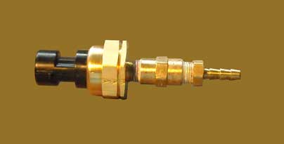
Speaking of the cooling system, I finally got a clear understanding of how the flushing port and quick-connect adaptor work. On my V6 E-TEC there are two ports on the back of the upper mid-section. The top port is an idle exhaust by-pass from the idle exhaust muffler. Below it is the overboard indicator outlet. The normal configuration on a 90-degree V6 is for this overboard indicator opening to have threaded into it an insert with a small orifice and nozzle that makes a cooling water confidence stream. This insert is important on the 90-degree V6 because it influences the pressure in the cooling system. If the insert and orifice are not in place, too much water will escape from the cooling system. If the orifice is blocked, too much cooling water will flow at low speeds. I think my stored error code (I mention above) was a result of a small pebble getting stuck in the insert and orifice.
You can remove the insert and the treads should match up with most hose fittings. This allows the engine to be flushed with fresh water. If you need to do this frequently, you can replace the insert and nozzle with a quick-connect flushing fitting. This fitting has a connector that snaps on to a mating connector you can attach to a hose, making flushing very simple. The quick-connect fitting also has a relief hole to regulate the pressure, like the normal confidence stream orifice. Because almost all my boating is in very pure, very clear, very clean Great Lakes fresh water, I don't have much need for flushing other than very occasionally; I don't plan to get the quick-connect adaptor. If you need to flush a 90-degree V6 E-TEC often, you might find the quick-connect adaptor to be useful. The part number is FLUSHING ADAPTOR P/N 775385. Note that it is intended only for the 90-degree V6 200- to 250-HP models. (Well, probably the 300-HP model, too, I would imagine.)
Here is the flushing adaptor:
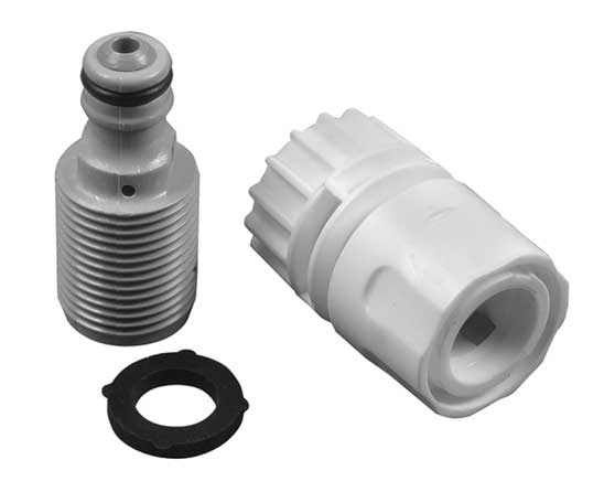
Please note that this adaptor is to be used only with the 3.3-liter and 3.4-liter E-TEC V6 engines. Do not use this adaptor on other E-TEC engines as damage to the engine could result from alteration of the cooling system temperature regulation.
Over the three seasons I have been running the E-TEC 225-HP engine, I have had two small problems with the cooling system. Both problems were caused by external influences. In the first week of running the engine, we were in the relatively cool water of Georgian Bay. I noticed that the engine was not warming up, and the engine block temperature gauge was reading well below the normal range when the engine was at idle speed for long periods. In an E-TEC 225-HP engine the engine temperature should rise to the 180-degree range when the engine has come up to operating temperature at idle speeds. When the throttle is advanced, the cooling system is opened for more cooling, and the engine temperature will drop to 140-degrees or less at cruising speeds. Something was wrong in this first week. The cause was soon found: a very small pebble or seed pod had been taken up in the cooling system and flushed through, landing in the overboard indicator stream nozzle, where the little pebble was partially blocking the flow. This was discovered by unthreading the overboard stream nozzle fitting, which can be done from the water when swimming, or could be easily reached from a dock. Apparently the overboard stream nozzle not only creates the stream of water but also influences the temperature regulation in the cooling system. With not enough water passing through the nozzle, the engine was getting too much cooling and the engine block would not warm up to proper temperature. Clearing the debris from the orifice of the nozzle cured that problem.
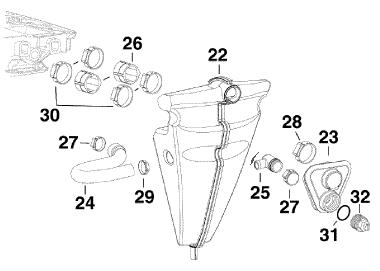
Early in the third season there was another cooling problem, and this also involved the overboard indicator stream nozzle. This problem occurred on our first use of the boat after winter storage. During storage the overboard indicator stream nozzle had been damaged. The boat must have been backed against a wall, and with the engine set perfectly vertical, the nozzle was the first point of contact. The plastic assembly had been broken, and in this condition was allowing too much cooling water to escape. This caused the engine to run very warm at idle and to trend upward in temperature toward overheat when running at cruising speeds. The cure was to replaced the broken nozzle fitting. Considering the sensitivity of the E-TEC 90-degree V6 cooling system to proper operation of the overboard stream nozzle, it would be a good plan to carry a spare. The overboard indicator fitting is PN 0436726 and retails for about $11.
Overboard indicator fitting is callout 32 above.
There is an error in the service manual and an omission in the drawings in the service manual regarding the path that cooling water takes on its way to the overboard indicator. The correct path is believed to be as follows:
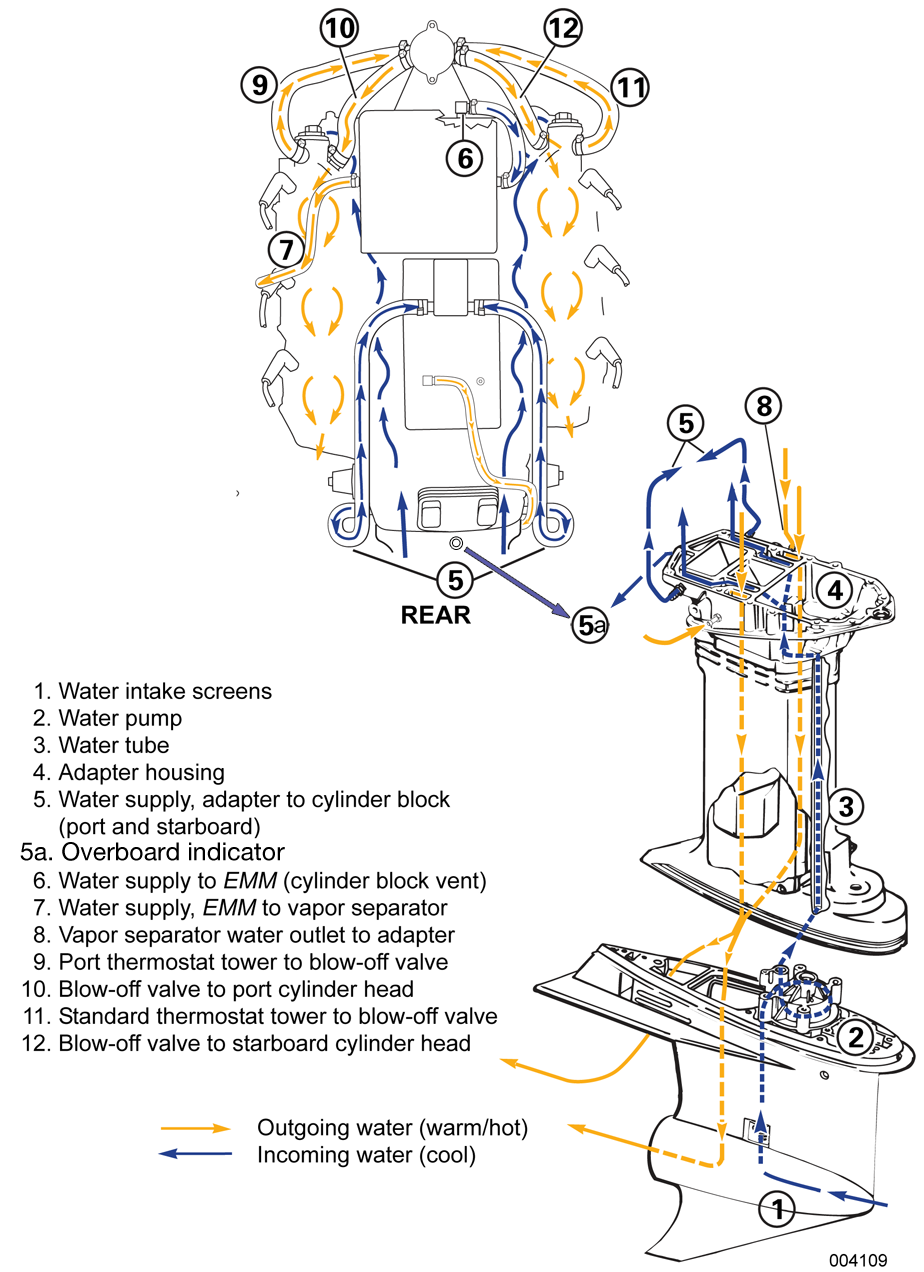
Cooling water path in E-TEC, revised from OEM drawing to show the feed to the overboard indicator at 5a. Click image for larger view.
The location of the overboard indicator in the cooling water path is different on the V6 90-degree block than on the V6 60-degree block. In the 90-degree block, some water flow and some water pressure is lost by the influence of the overboard indicator orifice in the initial path of the water pump output. The exact reasons for this design are not explained in the service manual. The presence of the overboard indicator on the pump output helps to immediately vent air from the cooling system as the cooling system beings to fill with water.
In the 90-degree engine the overboard indicator orifice is located in the cooling system near the point where the water pump supplies water flow to the system. For engine flushing, the orifice can be removed from the housing, and a water hose attached to it. Cooling water from a hose can then be supplied to the engine at this point. Because most of the cooling system passages are located downstream from the point where the overboard indicator is attached to the system, the flow of water to the engine block from a hose attached to the overboard indicator is going to be in the same direction as the normal water pump flow. There will be no flow reversal or back-flushing.
I also presume that when running the engine with cooling water supplied via the overboard indicator path, some water must flow down the copper tube to the water pump from the adaptor plate, and in this way the water pump impeller is provided with water so that it is not running dry. Once the engine starts, the water pump is going to try to expel the water. Since the water flow from the hose is going to keep filling the path above the water pump, I assume the impeller must stay wetted for the most part, and no damage occurs from operating the engine like this.
Water should appear to flow from the overboard indicator shortly after the engine is started. The appearance of the stream is a good initial indication that the water pump is working and cooling water flow has begun. Because the water in the overboard stream has not been circulated though the entire engine block, its temperature will not be especially hot, even when the engine temperatures have risen to their usual temperature range of over 160-degrees.
From its location close to the water pump, the influence of the overboard indicator orifice is better understood. In low speed operation, if the orifice flow is reduced due to blockage, more water flows into the engine block, which tends to cause over-cooling. In high speed operation, if the orifice flow is increased due to damage to the orifice causing it to leak or if the orifice is removed completely, too much cooling water will be diverted overboard; the engine will tend to overheat from under-cooling. Keeping the overboard indicator orifice intact and operating properly is very important to maintain engine cooling in the proper manner.
Installation of the impeller when servicing the water pump should follow the instructions provided with the Water Pump Service Kit, particularly with regard to how the vertical position of the impeller onto the drive shaft is locked in position. Refer to page-5 of the PDF document that shows the procedure.
What a pleasure it is to remove the cowling on this E-TEC V6. The weight of the cowling is very light, so it is easy to handle once you pull it off the engine. The latches work very well. The gaskets fit well. It is easy to get the cowling on and off. This is completely different from some other brands of outboard engines whose cowlings are extremely awkward to remove due to weight, size, poor latches, and very sticky gasket material. I make it a practice to take the cowling off engines at boat shows to see what is under the hood, and I have found many cowlings that were very difficult to move. In some cases, the cowlings were so stuck onto the engine or the latches so hard to operate, that I had to call a salesman over to assist because I was afraid I was going to break something. The E-TEC cowling fits well, is light, and has latches that are easy to operate and positively engage. But you probably already knew that.
Another rigging project was removing the SONAR transducer cable from a bundle of electrical cables running from the stern to the helm. About a year ago I began a project of moving all electrical cables from the below-deck rigging tunnel of my boat. Even though the rigging tunnel drains into the cockpit sump, the tunnel tends to accumulate a bit of water, with the result that the cables may be laying in water. I pulled out all the electrical cables, including the engine wiring harnesses, and ran them to the helm via a path under the gunwales, which kept them well above the water. All the electrical cables became bundled together, including the cable to the SONAR transducer.
Later, I noticed that when in deep water, more than 100-feet typically, the SONAR would begin to show some interference from the engine electrical signals. This began with my old 1992 V6 engine, and continued with the new E-TEC. I was somewhat surprised that the E-TEC was creating this interference, as I though perhaps it had eliminated any high-voltage signals in the harness. My guess is that the KILL circuit may be the cause of the interference, since this circuit (in the old engine) developed quite a high voltage, more than 300-Volts. In the E-TEC the circuit, carried on the BLACK with YELLOW Stripe conductor, carries about 55-Volts. Apparently this was enough voltage to cause interference with the SONAR when the SONAR detector gain was increased in deeper water. I did not try to diagnose or isolate precisely what was causing the SONAR interference. Instead I just re-routed the SONAR transducer cable back to the rigging tunnel, where it should be quite isolated from any other electrical signal.
Moving the SONAR transducer cable to a separate path from transom to helm has eliminated all interference to the SONAR from the engine.
By the way, I made my own cable to connect between the E-TEC engine and the RS-232 serial port of the diagnostic software. The details are shown in a separate article, along with possible sources of the parts. That article is a a very good source of information about the cable, the connectors, the wiring, and the diagnostic software. I also have these cable for sale. Contact me via email to inquire further.
I use the Keyspan USB HS-19A serial adaptor. Keyspan has drivers for both operating systems on my laptop, the Mac OS 10.5 and Windows-XP Professional. It is my experience that often it is well worth paying a few dollars more for a brand name device whose developers provide reliable driver software as opposed to getting the cheapest, no-brand, no-driver models.
The most recent Keyspan drivers are something of a dilemma. In order to get the Keyspan USB serial device to appear in the Windows environment on the Apple MacBook Pro, you must not plug-in the USB adaptor until after booting into the Windows environment.
I cannot offer any advice about using no-brand USB adaptors in a native Windows environment. Again, sometimes it makes sense just to spend a dollar or two more and get the mainstream, brand name device with good drivers. There is some recent (c.2012) anecdotal mentions that the USB-to-serial convertors with the FTDI chipset seem to work best with the latest versions of the Windows operating system (Windows 7) and the Evinrude Diagnostic Software, but I have not confirmed that myself. Since I am running Windows XP in an emulation environment, my set up is a bit out of the ordinary.
The location of various electrical rigging components and connectors for the V6 3.3-liter E-TEC engine are shown in the illustrations below.
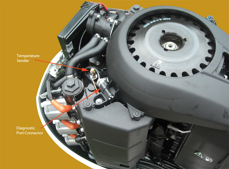
E-TEC 3.3-liter V6 diagnostic connector and temperature sender

E-TEC 3.3-lier V6 NMEA-2000 connector and water pressure sensor connector

Knock sensor on Starboard cylinder bank; a second knock sensor is on the Port bank.
A close inspection of the KNOCK SENSOR shows it is made by BOSCH in Germany. I suspect this sensor is commonly used in automobile applications. I recently was inspecting a 2011 four-cycle engine in an automobile and found a nearly identical sensor.
The location of the NMEA-2000 port connector and the diagnostic connector on the E-TEC 1.7-liter V4 engine are shown below. Don't confuse the Trim circuit connector for the diagnostic port; they use similar three-pin connectors.

E-TEC 1.7-liter V4 NMEA-2000 connector and diagnostic port connector. Photo credit: Paul Fithian
The location of the NMEA-2000 port connector on the E-TEC 1.3-liter I3 engine is shown below.

E-TEC 1.3-liter I3 NMEA-2000 connector. The dust cover cap is still in place. Photo credit: Evagelos Maragos
In the stock configuration there is no electronic monitoring of the E-TEC engine cooling system water pressure, however an electronic sensor can be added. The sensor monitors cooling water pressure from a tap into the engine block and sends the signal to the EMM. The EMM converts the signal to part of the engine parameters sent on the NMEA-2000 network from the E-TEC.
Monitoring water pressure in an engine is a good idea; it gives the operator a real-time look at the health of the cooling system. Water pressure should be in proportion to the output of the water pump. If the water pump output is low, water pressure should tend to be lower than the normal range. However, in order to know if the water pressure in below normal, one has to know what is normal.
Here are recommended or typical readings for many years and models of E-TEC engines which can be used as a guide for interpreting water pressure status:
| 2005-2008 | E-TEC Engine Water Pressure PSI as function of Engine RPM | ||||||||||
|---|---|---|---|---|---|---|---|---|---|---|---|
| MODEL | Idle | 1000 | 1500 | 2000 | 2500 | 3000 | 3500 | 4000 | 4500 | 5000 | 5500 |
| 40 - 60 HP | 4 - 5 | 5 - 6 | 7 - 9 | 10 - 11 | 14 - 15 | 15 - 17 | 16 - 18 | 16 - 18 | 14 - 16 | 12 - 14 | 10 - 12 |
| 75 - 90 HP | 4 - 5 | 10 - 11 | 12 - 14 | 15 - 17 | 16 - 18 | 16 - 18 | 13 - 15 | 15 - 17 | 16 - 18 | 19 - 21 | 20 - 22 |
| 60° V4 115 HP | 4 - 5 | 9 - 11 | 14 - 16 | 17 - 19 | 19 - 21 | 20 - 22 | 20 - 22 | 21 - 23 | 22 - 24 | 23 - 25 | 24 - 26 |
| 60° V6 150-200 HP | 4 - 5 | 9 - 11 | 14 - 16 | 17 - 19 | 19 - 21 | 20 - 22 | 20 - 22 | 21 - 23 | 22 - 24 | 23 - 25 | 24 - 26 |
| 90° V6 200-250 HP | 3 - 5 | 7 - 9 | 8 - 10 | 9 - 11 | 10 - 12 | 11 - 13 | 12 - 14 | 12 - 15 | 14 - 16 | 15 - 17 | 16 - 18 |
| 2010 | E-TEC Engine Water Pressure PSI as function of Engine RPM | ||||||||||
|---|---|---|---|---|---|---|---|---|---|---|---|
| MODEL | Idle | 1000 | 1500 | 2000 | 2500 | 3000 | 3500 | 4000 | 4500 | 5000 | 5500 |
| 40 - 65 HP | 4 - 5 | 5 - 6 | 7 - 9 | 10 - 11 | 14 - 15 | 15 - 17 | 16 - 18 | 16 - 18 | 14 - 16 | 12 - 14 | 10 - 12 |
| 75 - 90 HP | 5 - 6 | 10 - 11 | 12 - 14 | 15 - 17 | 16 - 18 | 16 - 18 | 13 - 15 | 15 - 17 | 16 - 18 | 19 - 21 | 20 - 22 |
| 60° V4 115-130 HP | 5 - 6 | 9 - 10 | 12 - 14 | 15 - 17 | 17 - 19 | 20 - 22 | 20 - 22 | 21 - 23 | 22 - 24 | 23 - 25 | 24 - 26 |
| 60° V6 150-200 HP | 4 - 5 | 9 - 11 | 14 -16 | 17 - 19 | 19 - 21 | 20 - 22 | 20 - 22 | 21 - 23 | 22 - 24 | 23 - 25 | 24 - 26 |
| 90° V6 200-250 HP | 3 - 5 | 7 - 9 | 8 - 10 | 9 - 11 | 10 - 12 | 11 - 13 | 12 - 14 | 13 - 15 | 14 - 16 | 15 - 17 | 16 - 18 |
| 90° V6 300 HP | 4 - 6 | 7 - 11 | 9 - 12 | 10 - 14 | 12 - 15 | 14 - 16 | 15 - 18 | 16 - 19 | 18 - 20 | 18 - 25 | 20 - 30 |
| RPM | Idle | 1000 | 1500 | 2000 | 2500 | 3000 | 3500 | 4000 | 4500 | 5000 | 5500 |
|---|---|---|---|---|---|---|---|---|---|---|---|
| MODEL | Water Pressure PSI | ||||||||||
| 40 - 65 HP 2-cylinder In-line |
4 - 5 | 5 - 6 | 7 - 9 | 10 - 11 | 14 - 15 | 15 - 17 | 16 - 18 | 16 - 18 | 14 - 16 | 12 - 14 | 10 - 12 |
| 65 - 90 HP 3-cylinder In-line |
5 - 6 | 10 - 11 | 12 - 14 | 15 - 17 | 16 - 18 | 16 - 18 | 13 - 15 | 15 - 17 | 16 - 18 | 19 - 21 | 20 - 22 |
| 90 HO - 130 HP 60° V4 |
≥ 5 | 9 - 11 | 12 - 14 | 15 - 17 | 18 - 20 | 20 - 21 | 20 - 22 | 21 - 23 | 21 - 23 | 21 - 23 | 21 - 23 |
| 150 - 200 HP 60° V6 |
4 - 5 | 9 - 11 | 14 -16 | 17 - 19 | 19 - 21 | 20 - 22 | 20 - 22 | 21 - 23 | 22 - 24 | 23 - 25 | 24 - 26 |
| 200 - 250 HP 90° V6 3.3L |
3 - 5 | 7 - 9 | 8 - 10 | 9 - 11 | 10 - 12 | 11 - 13 | 12 - 14 | 13 - 15 | 14 - 16 | 15 - 17 | 16 - 18 |
| 250 HO - 300 HP 90° V6 3.4L |
4 - 6 | 7 - 11 | 9 - 12 | 10 - 14 | 12 - 15 | 14 - 16 | 15 - 18 | 16 - 19 | 18 - 20 | 18 - 25 | 20 - 30 |
Below I have plotted the data for c.2010 engines for the 90-degree and 60-degree V6 models.

E-TEC water pressure as a function of engine speed; minimum recommended values plotted; for c.2010 engines.
With a readout of water pressure from my engine (with resolution to 0.01-PSI from my electronic water pressure sensor), and a copy of this chart posted on my dashboard, I can now monitor the health of the cooling system of my engine in real-time. However, going about it this way seems odd in 2010. With my E-TEC engine controlled by a modern engine management module (EMM), shouldn't the EMM keep an eye on water pressure for me? Perhaps there could be a few surplus processor cycles available every ten seconds to check the water pressure reading and compare it with the anticipated range shown above.
The monitoring of water pressure by the E-TEC EMM would have to be an optional feature, because (as far as I know) the standard configuration on an E-TEC is to not have an electronic monitor for cooling system water pressure. But, if an engine does have the optional electronic water pressure monitor installed, it would be nice if the EMM could monitor the pressure. Unfortunately, it does not. The EMM does not give any warnings for low water pressure, and the operator must keep an eye on it.
Below are several images showing the installation of the older-style brass water pressure sensor from BRP which connects directly to the EMM. The engine is a 2010 E-TEC 225-HP. I believe that the sensor was originally intended to thread directly into the engine block, but this approach was later abandoned. The latest part information I could find shows a similar sensor, but now the sensor is connected to the water pressure monitoring point by a short length of plastic hose.
To connect the sensor to the plastic hose requires a 3/8-inch NPT Female to 5/16-inch hose barb connector. I could not find that fitting at any local hardware stores, so I made my own using an extra coupling to convert a NPT Male connector that was in the plumbing supplies at my local hardware. The black plastic 90-degree connector is a BRP OEM part.

Water pressure sensor and some fittings to adapt to the cooling system line.
This assembled sensor is a bit longer than one using the proper fitting. I used Teflon pipe joint compound on the threads.
The electrical end of the sensor connects directly to the EMM using a supplied cable. The hose barb connects to the water pressure monitoring port on the engine block. It is best if the sensor is mounted above the water pressure monitoring point so that any water in the connecting hose tends to flow back into the engine and not into the sensor. Due to the constraints of the length of the cable I had and available places to install the sensor, I ended up mounting it by strapping it to the existing engine cooling water hoses at the rear of the engine. I bought a small OEM clip from BRP that is shown in the part breakdown, thinking it might be useful in attaching the sensor, but it turned out to be only large enough to hold the plastic hose.

The OEM sensor kit instructions call for mounting the sensor in a vertical orientation, but in the OEM engine service manual the shows the sensor installed horizontally, as I have done. The horizontal configuration has worked well for [now ten] seasons of use. The important detail to to make sure there is a downward path from the sensor to the engine block so that water is not retained in the sensor. This was particularly a problem in saltwater in earlier version of the sensor and its installation directly to the threaded port.
From the sensor the hose makes a gentle 180-degree bend downward and connects to the plastic hose barb that was already installed and was feeding my conventional water pressure gauge. This hose barb is threaded into a pre-threaded port into the cooling system. On the E-TEC 3.3-liter V6 block this port is located on the aft face of the engine and just below and just to the right of the "6" in the molded-in "V6" identifier in the casting. A threaded plug fills the port if no hose barb has been attached to it. I imagine that if you used a T-connector you could have both gauges working at the same time. This should keep water from collecting in the sensor. In any event, just about all of my boating is in fresh water, so I don't expect much corrosion to occur.
The method of mounting of the sensor to the hoses is not ideal, and I will monitor it to see if there is any wear on the hoses. The white nylon cable tie shown above is bearing on the portion of the hose which has the Oetiker clamp binding on it, and I don't expect it to cause much harm to the steel clamp. The yellow cable tie is bearing on the hose, and I will watch it to see if it begins to cut into the hose. I may end up installing some rubber material between the sensor and that large rubber hose to protect them both.
The recommended OEM mounting in the installation instructions has the sensor suspended in mid air and retained only by that small plastic clip and the electrical connector. I don't think that configuration is particularly good.
Please note that if a water pressure sensor is installed and connected to the EMM, the EMM must be re-configured to use that data input from the sensor. The EV-Diagnostics software must be used to set the engine EMM to be aware of the sensor, and also to configure for the particular sensor in use. There are different pressure ranges for different sensors. If the E-TEC owner does not have the EV-Diagnostics software or is not familiar with using it, this change in EMM set up should be done by a dealer.
I have tested several propellers with the E-TEC 225-HP engine on my 1990 Boston Whaler REVENGE 22 Walk-Through with Whaler Drive. I will give details from the testing of the best of the propellers.
The propeller which has been used the most is a Mercury MIRAGEplus three-blade with 17-pitch. The MIRAGEplus gives good acceleration and top speed, shows no sign of blowing out in any running conditions, and has provided very good fuel economy.
Here are some data from tests of a 15.5 x 17 Mercury MIRAGEplus propeller on my Boston Whaler REVENGE 22 Walk-Through with Whaler Drive and a 2010 Evinrude E-TEC 225-HP engine. The data was collected in calm water condition on Lake Michigan near the northern end of Grand Traverse Bay in June 2010. The boat had over 1/2-FULL fuel tank, all its canvas was up, and there was a heavy load of cruising gear. The boat speed was taken from GPS data. The engine speed was taken from a digital tachometer. The fuel flow was taken from the engine's own instrumentation. The engine was mounted one-hole up.
June 2010
MIRAGEplus 15.5 x 17
RPM    MPH    GPH    MPG
 500   3.2    0.21  15.2
 600   3.6    0.34  10.6
 900   5.2    0.58   9.0
1000   5.5    0.68   8.1
1000   5.8    0.70   8.3
1100   6.2    0.81   7.65
1350   6.9    1.2    5.9
1550   7.8    1.7    4.5
3350  18.5    8.1    2.3
3400  19.8    8.3    2.4
3450  23.5    8.5    2.76
3450  24.0    8.5    2.8
3550  25.0    8.7    2.85
3800  27.4    9.88   2.78
3800  27.6    9.9    2.8
3800  28.1    9.85   2.85
3950  29.2   10.8    2.8    Trim at 23%
4000  29.8   10.7    2.8
4000  30.0   10.7    2.8
4250  32.3   11.8    2.7
4500  34.1   12.5    2.7
4750  36.0   14.1    2.6
5000  38.1   16.0    2.4
5450  42.1   20.2    2.1
5500  42.8   21.0    2.0
5550  43.2   20.6    2.1
Here is a plot of that data:
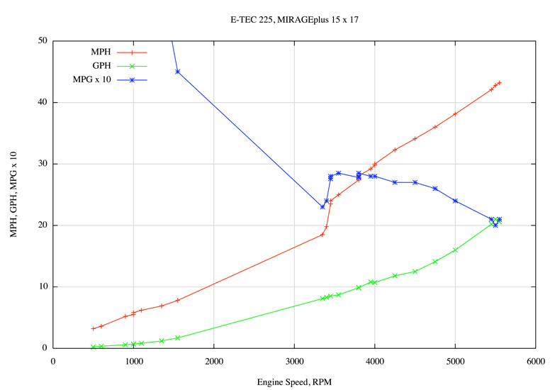
As you can see, the slow speed fuel economy data is off the chart. At idle speed, 500-RPM, the fuel economy is about 15-MPG. It takes five hours to burn a gallon of fuel at that speed. The optimum cruising speed is between 25 and 30-MPH, where the fuel economy stays fairly constant at 2.8-MPG. The boat can stay on plane as slow as 18-MPG, but the fuel economy is not good.
The MIRAGEplus propeller was run with the Performance Ventilation System holes filled with full plugs. The engine was mounted one-hole up. The MIRAGEplus propeller did not show any signs of losing grip or blowing out at any time. We intentionally took some high speed turns with the engine trimmed out, and the propeller did not ventilate. We ran the boat is a variety of sea conditions. The MIRAGEplus propeller did not ventilate when running into larger head seas while on a slow planing speed of around 14-MPH.
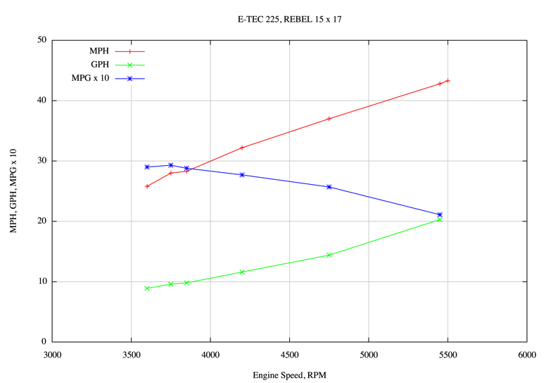
I have conducted some sea trials with a BRP REBEL 17-pitch propeller, a three-blade design that is similar to the Mercury MIRAGEplus. The data below was collected in the fall of 2009. The boat canvas was up and we were running into small head seas. The engine was mounted one-hole up. Crew was two people aboard. The overall boat weight was a bit lighter than our normal heavy cruising load, as there was no cruising gear in the cabin and no coolers in the cockpit. The temperature of the air and water was in the low 50-degree range. Speed data is from a GPS receiver. Fuel flow rate is from the engine's EMM data. Slip calculation is from my own propeller calculator.
October 2009
RPM     MPH     GPH     MPG     SLIP
3550    25.4    8.6     2.95    17.8
3600    25.8    8.9     2.90    17.6
3750    28.0    9.6     2.92    14.2
3850    28.3    9.8     2.88    15.5
4200    31.7    11.6    2.77    11.9
4750    37.0    14.4    2.57    10.5
5450    42.8    20.3    2.11     9.7
5500    43.3                     9.5
I am particularly pleased with two measurements. First, the fuel economy at a moderate planing speed of 25-MPH is excellent, almost 3-MPG. Second, the propeller SLIP declines to less than ten-percent at maximum speed, which is a good indication of proper propeller selection. The REBEL 17 looks like a good candidate for a propeller for this combination. Here is a plot of the data:
Regarding trim, the REBEL 17 propeller seems to be quite tolerant of being run with high trim settings, that is, it does not seem to lose grip. I have another 17-inch-pitch propeller, an older SST 17, which cannot tolerate being run with very much trim out, and you can hear the engine speed jump up several hundred RPM when you trim the engine out because the propeller is losing grip. With the REBEL 17 I don't notice that happening, and the propeller stays hooked up even with high trim settings. When the SST 17 begins to lose grip, the fuel economy suffers.
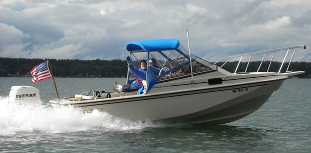
The last data point, the 43.3-MPH top speed, was running with the wind and waves, as we were trying to out race a rain shower approaching from our stern. Below is a nice picture taken by another boat in our fleet as were were running together at about 42- to 43-MPH. The air temperature was about 52-degrees-F, or about 11-degrees-C.
In late October of 2009 a BRP Cyclone 17-pitch propeller was briefly tested. The test conditions were slightly different than the norm. The boat had no canvas rigged, reducing wind resistance. The fuel load was high, 7/8-FULL tank. There was a light wind and minimal waves. Crew was again two people. Here is the data collected in this brief test:
Cyclone 17 four-blade October 2009
Downwind
RPM     MPH     GPH     MPG     SLIP
3800    26.7    9.7     2.75    19.3
3850    27.4    9.8     2.8     18.2
4200    31.9    11.4    2.8     12.7
5500    44.0    21.3    2.07     8.1
5550    44.4    21.2    2.1      8.1
Upwind
RPM     MPH     GPH     MPG     SLIP
2600    12.9    6.3     2.15    43.0
3250    19.6    8.3     2.4     30.7
3500    26.6    9.9     2.7     12.7
4150    30.6    11.5    2.7     15.3
5350    42.3    *       *        9.1
Crosswind
RPM     MPH     GPH     MPG     SLIP
5450    44.4    20.4    1.7      6.4
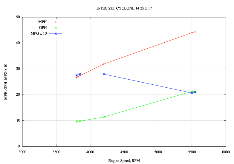
The CYCLONE results are somewhat unexpected. First of all, the boat seemed really fast with this propeller. It hit a new high-speed mark, 44.4-MPH. This was probably influenced by the lower wind resistance from having all the canvas down and the cold air and water. Second, the fuel economy did not seem to be as good as expected. The MPG topped out at 2.8, which is not bad, but not as good as the REBEL had shown. The problem may be I did not get good data below 25-MPH. The boat seemed so fast with this propeller that it just did not want to run at that speed. I am remarking about the data because generally you'd expect a four-blade propeller to be a bit slower than a three-blade, and also to give better mid-range fuel economy. This test seemed to produce the opposite results. This run was really more for the purpose of getting stabilized fuel to circulate through the fuel system, and the propeller testing was not done as extensively or carefully as in the past. We were running on an inland lake, and at 40-MPH you run out of lake rather fast, so we did not always get the trim optimized.
In propeller testing it is important to maintain the test conditions as constant as possible. However, this is not always possible. In the tests above two kinds of fuel were used. In the test with the REBEL propeller the fuel used was a mixture of gasoline and gasoline blended with ethanol, and I estimate that over 60-percent of the tank volume was non-ethanol gasoline. In the test with the CYCLONE propeller the fuel used was again a mixture, but now the ethanol fuel was likely more than 60-percent of the tank. It is hard to give these figures with much precision, because due to the lack of proper labeling of gasoline fuels, the ethanol content of gasoline purchased in Michigan is something of a mystery, unless greater than 10-percent. (A few years ago, in a drive concealed as an environmental movement, the ethanol lobbyists succeeded in modifying the existing labeling requirements in the State of Michigan for gasoline to remove notice of ethanol when blended at less than 10-percent. Don't let this happen in your state.)
The difference in the observed fuel economy at similar boat speeds, and again, the data is a bit imprecise, seem to be on the order of a variation of 0.1 to 0.2-MPG in a range of 2.7 to 2.9-MPG. This variation represents a change of about 3-percent to 7-percent in fuel mileage. Some of this change may be due to the influence of the gasoline. It is widely known that the energy content of gasoline diluted with ethanol is lower than pure gasoline. E10 has only 0.9672 as much energy as pure gasoline. The influence of this has been estimated for E10 fuel to be a reduction in fuel mileage of 3-percent. It is possible that a change in fuel played a role in reducing the fuel economy observed with the CYCLONE propeller. In making fuel mileage comparisons, the data would be more useful if collected using the same fuel for the engine in all tests.
Other than the minor cooling system problems I mentioned above, my three seasons with an E-TEC have been trouble-free. However, there are two items that have been mentioned by other users which I think are prudent to pass along.
E-TEC owners who operate in saltwater have reported that the stainless steel threaded fasteners used on the water pressure relief valve have been damaged by corrosion. With very warm--hot--saltwater flowing in the engine cooling system, a stainless steel fastener is put to the test. In some cases the OEM hardware has not stood up. The water pressure relief valve on the V6 is located at the top, rear, center of the engine block, in front of the EMM. (The assembly is clearly visible in the photograph that shows the connector locations; see above.) Although mine are in perfect condition, some users have reported problems. The diagram below shows the fasteners in detail:
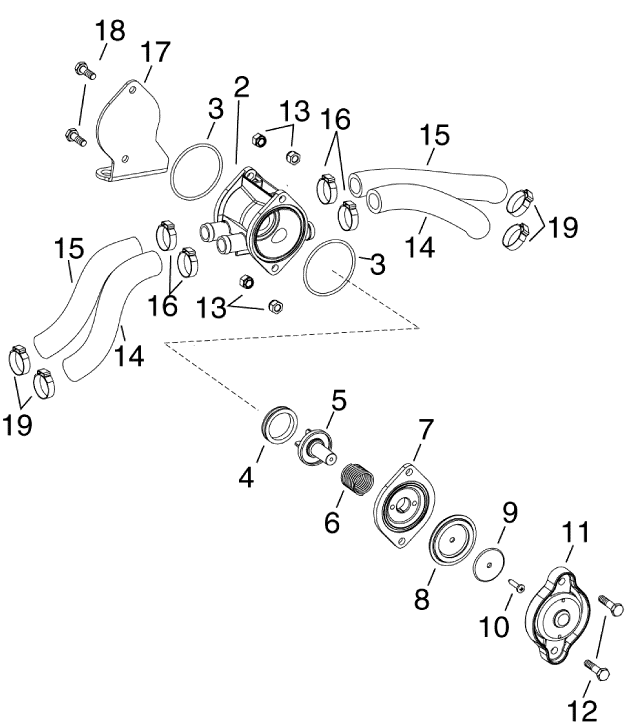
The affected fasteners are identified above by callouts 12, 13, and 18.
It is prudent to check the condition of these fasteners before they might become corroded and fused together.
The E-TEC EMM senses the exhaust system back pressure to help control engine fuel, air, and spark parameters. The sensor is internal to the EMM, but it connects via a rubber hose to a fitting that protrudes into the exhaust area of the midsection of the E-TEC engine. At the end of the fitting there is an orifice. The sensor is calibrated for pressure measurement through this orifice. As you might imagine, the exhaust is hot, and, under some conditions there may be soot (carbon) particles in the exhaust. The exhaust back pressure fitting in the exhaust path is shown in the diagram below as callout number 2. The part number is 5007618, and the retail price is $40.80.
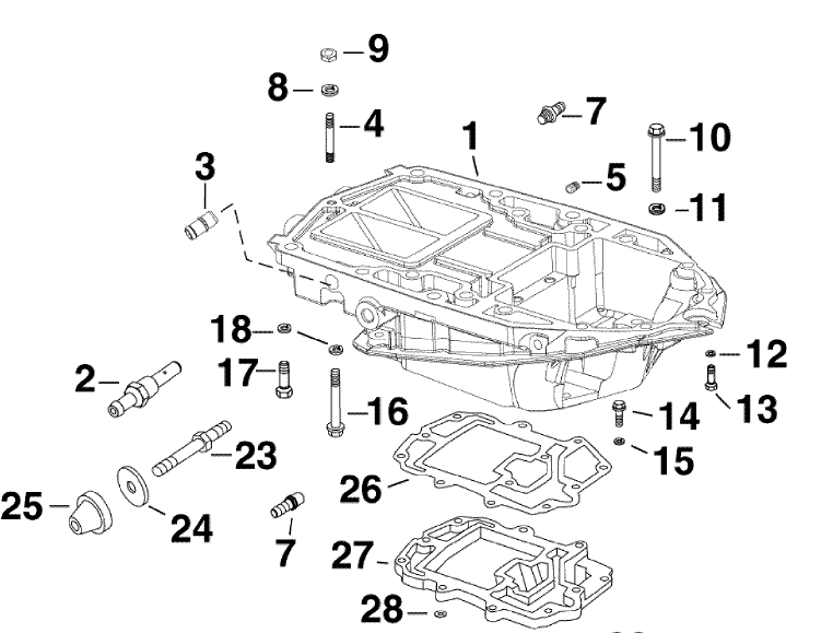
Callout 2 is the exhaust back pressure fitting. A rubber hose connects this fitting to the exhaust back pressure sensor inside the EMM.
Some E-TEC owners have reported that the exhaust back pressure fitting has become contaminated with soot or carbon, with the result that the metal of the fitting has been subjected to burning and the orifice as been burned off or completely clogged. Either situation leads to the EMM sensing the wrong exhaust back pressure, which leads to poor operation of the engine.
Checking of the condition of the exhaust back pressure fitting is part of the 300-hour maintenance recommended by Evinrude. The tendency for the exhaust back pressure fitting to become damaged seems to be related to the type of oil being used. Mechanics report that with XD100 oil there is little or no incidence of problems. E-TEC engines run on off-brand TCW3 oil tend to have more problems. It is prudent to keep watch on this fitting if you see any running problems with the E-TEC or if there is a sign of excessive soot. Engine operating temperature also affects the production of soot; an engine running at the proper temperature and with proper loads does not tend to produce much soot in the exhaust.
More discussion occurs in a thread.
Copyright © 2012, 2019 by James W. Hebert. Unauthorized reproduction prohibited.
This HTML document is served to you from continuousWave
Author: James W. Hebert
This article first appeared April 5, 2012.
This HTML has been checked by https://validator.w3.org/nu/.